Download
1 / 29
290 likes | 458 Views
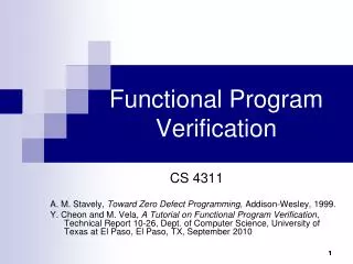
Functional Verification of Dynamically Reconfigurable Systems (Version 2.3b). Mr. Lingkan (George) Gong, Dr. Oliver Diessel The University of New South Wales, Australia. Outline. Objectives & Motivation Challenges in Verifying Dynamically Reconfigurable Systems (DRS)

E N D
Functional Verification ofDynamically Reconfigurable Systems(Version 2.3b) Mr. Lingkan (George) Gong, Dr. Oliver Diessel The University of New South Wales, Australia
Outline • Objectives & Motivation • Challenges in Verifying Dynamically Reconfigurable Systems (DRS) • Proposed Solution: The ReSim Library • Example Designs • Conclusions
Objectives & Motivation • Dynamically Reconfigurable Systems (DRS) • Improved flexibility • Better resource utilization
1 bug/6 lines of RTL code Objectives & Motivation • Functional Verification • Bottleneck of all hardware designs • Most costly bugs occur in system integration stage • DRS designs Involve activities that don’t exist in static designs (e.g., module swapping, … ) • It is essential to perform simulation-based verification of Dynamically Reconfigurable Systems (DRS)
Objectives & Motivation • “Partial Reconfiguration itself can not be simulated … ” • Xilinx UG702 (Partial Reconfiguration User Guide) • Can simulate Static + A; Static +B; But not the process of swapping out A and swapping in B • Objective • Support the simulation of the reconfiguration process • Support the simulation and functional verification of integrated Dynamically Reconfigurable Systems (DRS) Dynamically Reconfigurable System (Static part) Dynamic part: Module A Dynamic part: Module B Dynamic part: Module B
Objectives & Motivation • Focus on detecting functional bugs • e.g. Cycle mismatch • Assuming there is no timing violation, no errors in the bitstream, no glitch in the reconfiguration process • Focus on systematic verification • Correctly verified sub-systems, while necessary, are not sufficient • Recommend to simulate the design BEFORE running it on the target device
Challenges in Verifying DRS • DRS-specific design considerations
Challenges in Verifying DRS • DRS-specific bugs • BEFORE Reconfiguration Handshake errors (e.g., deadlock) Fail to save module state … • DURING Reconfiguration: Errors in bitstreams (e.g., if a design “assemble” bitstreams at run time, bugs can be introduced to the generated bitstreams) Errors in transferring bitstreams (e.g., traffic contention, encryption …) Fail to isolate the module undergoing reconfiguration … • AFTER Reconfiguration Errors in resetting the module Errors in state restoration …
Challenges in Verifying DRS • Accuracy v.s. Productivity • Simulation accuracy Modeling the entire FPGA fabric Models for the FPGA fabric not available Even if available, it is not efficient to simulate the FPGA fabric (Low Productivity)
Challenges in Verifying DRS • Accuracy v.s. Productivity • Simulation productivity DO NOT model the FPGA fabric Does not model bitstream traffic Assume zero or constant reconfiguration delay Does not trigger module swapping Does not model spurious module outputs Low accuracy
Challenges in Verifying DRS • Accuracy v.s. Productivity • Simulation accuracy DO model the FPGA fabric • Simulation productivity DO NOT model the FPGA fabric • It is essential to balance “accuracy” & “productivity” when simulating partial reconfiguration
ReSim • Core idea • Model the fabric at such a level of detail that is just enough for RTL simulation of DRS
ReSim • Simulation-only bitstreams (SimB) • Capture the essence of a real bitstream, but with reduced size
ReSim • Capabilities and Limitations • BEFORE Reconfiguration Handshake errors (e.g., deadlock) Fail to save module state … • DURING Reconfiguration: Errors in bitstreams (e.g., if a design “assemble” bitstreams at run time, bugs can be introduced to the generated bitstreams) Errors in transferring bitstreams (e.g., traffic contention, encryption …) Fail to isolate the module undergoing reconfiguration … • AFTER Reconfiguration Errors in resetting the module Errors in state restoration … RED: Only on Target device BLUE: Only by ReSim GRAY: More Efficient by ReSim
ReSim • Capabilities and Limitations • ReSim assists in testing fabric-independent part of the design • After simulation, test & debug fabric-dependent part on the target device (using Chipscope)
ReSim • Reusability • Codegen: automatic generation of artifacts • OO: override the default behavior of artifacts
Example Designs • Example Designs • XDRS.QUICKSTART • XDRS.SINGLE • XDRS.MULTIPLE • FPCIe • State_Migration • Derived from ReSim case studies • See “ReSim Case Studies” for more information on development progress, bugs detected and lessons learned.
Example Design: XDRS • XDRS: a generic DRS computing platform • Similar to Erlangen Slot Machine, a general-purpose reconfigurable compute engine (Bobda et al. FCCM 2005)
Example Design: XDRS • Example simulation waveform • @t1: Sync, @t2: Transfer a bitstream, @t3: Extract RRID/RMID@t4: Inject errors, @t5: Swap module, @t6: Reset
Example Design: XDRS • Example bug that was detected • Hold the "reset" signal of a module during reconfiguration
Example Design: XDRS • Regression and coverage analysis
Example Design: FPCIe • FPCIe • Derived from Fast PCIe configuration (XAPP883) • ~3500 lines of Verilog code + Coregen code (the PCIe endpoint) • Integrate ReSim with the original testbench • 150 lines of Tcl script (120 IO signals) • 10 lines of Verilog code to instantiate the generated artifacts • 110 lines of Verilog code to send SimBs to the DUT
Example Design: FPCIe • Example simulation waveform • @t1: Transfer a bitstream over PCIe, @t2: Swap module, @t3: Application logic starts operating
Example Design: State_Migration • State_Migration • Derived from Microprocessor Peripheral reconfiguration (UG744) • Modified the hardware to use PPC440 & xps_icapi • Modified the software to save RM state via ICAP • The modified software is composed of fabric-independent C code and fabric-dependent C code
Example Design: State_Migration • Example simulation waveform • @t1: Read ICAP IDCODE (ReSim’s IDCODE=0x0c1b2011)@t2: Issue GCAPTURE@t3: Configuration readback
Conclusions • Accuracy v.s. Productivity
Conclusions • It is essential to simulate partial reconfiguration • Activities such as bitstream traffic, triggering condition, state saving and restoration, isolation of the reconfigurable region, … • It is essential to balance accuracy & productivity • Modeling the FPGA fabric is not productive • MUX-based simulation is not accurate • ReSim • Models the fabric at such a level of detail that is just enough for RTL simulation of DRS • A reusable simulation library
More Infomation • ReSim Home Page • http://code.google.com/p/resim-simulating-partial-reconfiguration/ • ReSim Document • ReSim User Guide • ReSim Case Studies • Contact • Mr. Lingkan Gong, http://code.google.com/p/resim-simulating-partial-reconfiguration/wiki/Lingkan_Gong • Dr. Oliver Diessel, http://www.cse.unsw.edu.au/~odiessel/


![[2.3B] Divide](https://cdn1.slideserve.com/1892433/2-3b-divide-dt.jpg)