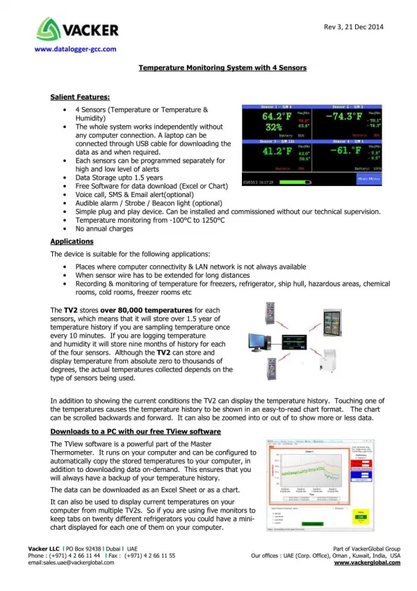
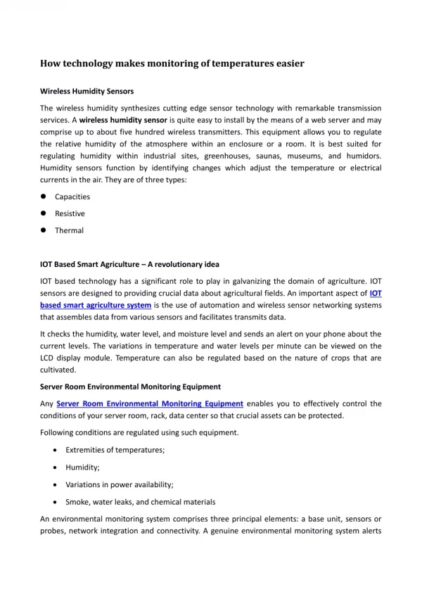
Download

1 / 13
140 likes | 205 Views
72. TEMPERATURE SENSORS. Figure 72-1 A typical engine coolant temperature (ECT) sensor. ECT sensors are located near the thermostat housing on most engines. Figure 72-2 A typical ECT sensor temperature versus voltage curve.

E N D
72 TEMPERATURE SENSORS
Figure 72-1 A typical engine coolant temperature (ECT) sensor. ECT sensors are located near the thermostat housing on most engines.
Figure 72-2 A typical ECT sensor temperature versus voltage curve.
Figure 72-3 A typical two-step ECT circuit showing that when the coolant temperature is low, the PCM applies a 5-volt reference voltage to the ECT sensor through a higher resistance compared to when the temperature is higher.
Figure 72-4 The transition between steps usually occurs at a temperature that would not interfere with cold engine starts or the cooling fan operation. In this example, the transition occurs when the sensor voltage is about 1 volt and rises to about 3.6 volts.
Figure 72-5 Measuring the resistance of the ECT sensor. The resistance measurement can then be compared with specifications. (Courtesy of Fluke Corporation)
Figure 72-6 When the voltage drop reaches approximately 1.20 volts, the PCM turns on a transistor. The transistor connects a 1-kΩ resistor in parallel with the 10-kΩ resistor. Total circuit resistance now drops to around 909 ohms. This function allows the PCM to have full binary control at cold temperatures up to approximately 122°F, and a second full binary control at temperatures greater than 122°F.
Figure 72-7 An ECT sensor being tested using a digital meter set to DC volts and record mode to capture the data shown. A chart showing the voltage decrease of the ECT sensor as the temperature increases from a cold start. The bumps at the bottom of the waveform represent temperature decreases when the thermostat opens and is controlling coolant temperature.
Figure 72-8 The IAT sensor on this General Motors 3800 V-6 engine is in the air passage duct between the air cleaner housing and the throttle body.
TECH TIP: Quick and Easy ECT Test To check that the wiring and the computer are functioning, regarding the ECT sensor, connect a scan tool and look at the ECT temperature display. STEP 1 Unplug the connector from the ECT sensor. The temperature displayed on the scan tool should read about -40. NOTE: -40° Celsius is also -40° Fahrenheit. This is the point where both temperature scales meet. STEP 2 With the connector still removed from the ECT sensor, use a fused jumper lead and connect the two terminals of the connector together. The scan tool should display about 285°F (140°C). This same test procedure will work for the IAT and most other temperature sensors.
TECH TIP: Poor Fuel Economy? Black Exhaust Smoke? Look at the IAT If the intake air temperature sensor is defective, it may be signaling the computer that the intake air temperature is extremely cold when in fact it is warm. In such a case the computer will supply a mixture that is much richer than normal. If a sensor is physically damaged or electrically open, the computer will often set a diagnostic trouble code (DTC). This DTC is based on the fact that the sensor temperature did not change for a certain amount of time, usually about 8 minutes. If, however, the wiring or the sensor itself has excessive resistance, a DTC will not be set and the result will be lower-than-normal fuel economy, and in serious cases, black exhaust smoke from the tailpipe during acceleration.
FREQUENTLY ASKED QUESTION: What Exactly Is an NTC Sensor? A negative temperature coefficient (NTC) thermistor is a semiconductor whose resistance decreases as the temperature increases. In other words, the sensor becomes more electrically conductive as the temperature increases. Therefore, when a voltage is applied, typically 5 volts, the signal voltage is high when the sensor is cold because the sensor has a high resistance and little current flows through to ground. - SEE FIGURE 72–9 . However, when the temperature increases, the sensor becomes more electrically conductive and takes more of the 5 volts to ground, resulting in a lower signal voltage as the sensor warms.