Download
1 / 23
240 likes | 374 Views
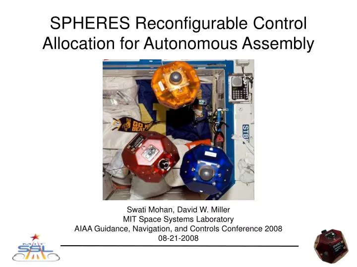
SPHERES Reconfigurable Control Allocation for Autonomous Assembly. Swati Mohan, David W. Miller MIT Space Systems Laboratory AIAA Guidance, Navigation, and Controls Conference 2008 08-21-2008. Outline. Motivation Reconfigurable control overview SPHERES Overview Control allocation methods

E N D
SPHERES Reconfigurable Control Allocation for Autonomous Assembly Swati Mohan, David W. Miller MIT Space Systems Laboratory AIAA Guidance, Navigation, and Controls Conference 2008 08-21-2008
Outline • Motivation • Reconfigurable control overview • SPHERES Overview • Control allocation methods • Testing Results • Conclusions
Space Solar Power Station Space Telescope (ex. JWST) International Space Station Motivation: Autonomous Assembly • On-orbit assembly is an enabling technology • Challenges: Sequencing, Accurate Sensors & Actuators, etc • Current methods high in risk, cost, and time • Human EVAs, Tele-operated robotic arms • Limited to Low Earth Orbit • Desire to fully automate assembly process using robotics • Additional Challenges for Autonomous Robotic On-Orbit Assembly: • Design challenges • Autonomy • Autonomous Control and Reconfiguration • Systems challenges • No unified design principles or guidelines • Requirements may vary drastically with application Address reconfigurable control system design for autonomous robotic on-orbit assembly.
Initial Config Final Config Assembler Assembly Sequence Tug Only Tug + Seg Tug + Seg + Base Tug Only, Base Tug + Seg, Base Tug Only, Base Motivation: Control Allocation Issue: How to maintain performance at each docking/undocking to complete assembly, in spite of large mass and stiffness property variations? Suppose we want to … assemble N segments from an initial to final configuration, using a propellant tug with docking capability • Configuration: static configuration for a given time period, (eg. Tug Only, Tug + Segment) • Transition: change from one configuration to another (eg. Docking: Tug Tug + Segment) • Single Control System Tug • Need to design control system to handle all configurations • Want to maintain performance (ie stability, efficiency, accuracy) and versatility (ex. minimal hardcoded transitions and properties)
Reconfigurable control • Reconfigurable control – on-line model calculation: • Identify a vector of properties p upon which the model depends • Develop the analytic expressions to calculate the model (N) based on the vector p • At each transition, update the vector p • At each update of the vector p, re-calculate the model N based on the analytic expressions • Use the model N to calculate the control input (u) • Goal: Implement and Demonstrate on hardware Currently implemented p
SPHERES Overview - X Thruster Ultrasonic Receivers Lexan Shell Pressure Gauge Adjustable Regulator CO2 Tank + Z Satellite body axes - Y Control Panel
Control Allocation Methods • Assumptions of SPHERES baseline control allocation algorithm • Symmetric thruster placement • Center of mass fixed in center of thruster envelope • Fixed thruster configuration • Intermediate reconfigurable control allocation algorithms • Mixer A: Reconfigurable to thruster configuration • Assumes symmetric thrusters • Application – Docking to an active payload • Mixer B: Reconfigurable to center of mass location • Assumes fixed thruster configuration • Application – Docking to a passive payload • Mixer C: Reconfigurable to thruster configuration AND center of mass location • Generalized mixer • Removes all assumptions of baseline SPHERES control allocation algorithm
Inputs Outputs Reconfigurable Calc location of thruster (rcm) from rgc and CM Invert to get full Mixing Matrix Thruster Config (rgc, F) Torque = rcm x F Mapping Matrix Thruster on / off times Control Vector Calculate thruster forces & durations Original Control Vector Thruster on / off times Calculate thruster forces & durations (Hardcoded) Mixing Matrix Mixer C Implementation Control Allocation Algorithm on SPHERES
Testing • Objectives: • Stability: actuation of control input stabilizes the system • Accuracy: can achieve ± 2cm position control required for docking • Fuel Performance: fuel usage is improved by updating the model • Four test configurations • C1: SPHERE only • C2: SPHERE + Battery Proof Mass • C3: SPHERE + SPHERE Proof Mass • C4: 2 SPHERE attached (joint firing) • Test Cases • Attitude Control only • Position and Attitude Control
Results: Attitude Control C4 • Two SPHERES attached by Velcro. Only one can fire thrusters. • Two 90˚ Z axis rotations • 1st rotation OLD gains, O=47˚ • 2nd rotation NEW gains, O=41˚ • Two SPHERES attached by Velcro. Both can fire thrusters. • Two 90˚ Z axis rotations • 1st rotation OLD gains, Ts = 40s, O=30˚ • 2nd rotation NEW gains, Ts = 20s, O=20˚ Fuel usage given in percent usage of tank (170g CO2 in one tank) 1.77% 2.77% 1.22% 1.18%
Results: Position & Attitude Control • C4: 2 SPHERES attached, joint thruster firing • Targets: [0.4, 0, 0], [0.4, 0.4, 0], [-0.4, -0.4, -0.4],
Results: Position & Attitude Control C1: Satellite Only C4: Two Satellite Joint Firing
Results: Position & Attitude Control • C3: SPHERES plus SPHERE Proof Mass • Targets: [0.4, 0, 0], [-0.4, -0.4, -0.4], [0.4, 0.4, 0]
Results: Position & Attitude Control C1: Satellite Only C3: Satellite with Sat Proof Mass
Conclusions / Future Work • Motivation: • Update model on-line during a test to account for configuration changes • Want to maintain control performance in terms of stability, efficiency, and accuracy • Conclusions • Demonstrated reconfiguration for attitude and position • In process of increasing accuracy in 2 SPHERE case to be sufficient for docking and assembly • Future Work • Demonstrate reconfiguration in full assembly test • Introduce flexible dynamics • Augment to include sensor reconfiguration
Complete A-Priori Information No Information Control Reconfiguration Methods • ISS Attitude Gain Scheduling (Parlos & Sunkel) • Implemented for docking, series of equilibrium states • Assumes look-up table for mass properties at each equilibrium state • Multiple model reconfiguration (Maybeck and Stevens) • Multiple Kalman filters for each operational states • Transition between models is seamless, based on analysis of measurement residuals • System Identification (Wilson et al) • Maneuvers to determine model (mass and inertia) using recursive least squares • Assumes thruster maneuvers • On-line model calculation • Takes in a properties vector (eg. p = [Mass, Inertia, Center of Mass, …] ) • Generates the model from the list of properties • Uses the model to generate the appropriate control input
Approach State Space ModelGeneral • Mass, Inertia, • Center of Mass (CM), • Thruster locations w.r.t CM • Thruster Number & Directions • Thrusters available • Controller Gains • Sensor locations w.r.t CM • Sensors available • Estimation statistics
On-line Model Calculation (2/3) • Example of analytic expressions (similar for position gains) • Assumes small cross products for inertias • Attitude Gains: K = f(p) PD controlPID control
On-line Model Calculation (3/3) • Analytic expressions for thruster configuration update • Mixing matrix (M): 6 (forces and torques) by num thrusters • Inverse of Mixing matrix converts control vector to thruster forces Inverse of Mixing Matrix Control vector input Thruster forces
C1: Satellite Only Results: Position & Attitude (1) C2: Satellite Plus Batt Proof Mass