Download
1 / 19
190 likes | 305 Views
AID–EMC: Low Emission Digital Circuit Design. Update of the “Digital EMC project”. January 19th, 2006. Junfeng Zhou Wim Dehaene KULeuven ESAT-MICAS. Outline. Circuit structure 2. Maple simulation 3. Spectre simulation 4. Future work. Coupling problem !.

E N D
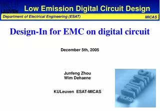
AID–EMC: Low Emission Digital Circuit Design Update of the “Digital EMC project” January 19th, 2006 Junfeng Zhou Wim Dehaene KULeuven ESAT-MICAS
Outline Circuit structure 2. Maple simulation 3. Spectre simulation 4. Future work
Coupling problem ! Cgs1,2≈ Cgd1 ∆ Vbias ∆ VDD_input
Why new structure ? Simple Driving capability Miller effect on compensation capacitor Cascode device: decrease coupling from VDD_input to VDD provided that Vbias is biased as a low impedance node
Stability analysis φ≥60° Worst case Stability as a function of Iload (26.7u A ~ 72m A) Raux=1.852K , Caux=20p
Maple calculation An input current step of 1 mA and 100-ps rise time was used for the calculation and simulation
Comparison with old structure ~10reduction !! Old structure New structure
Spectre simulation – TF H(s)=Idd(s)/Iout(s) Future: Theoretical Expression of TF TF as a function of Caux
Relation with Gabarit ? ? emission limit example: H-12-n-O Source: from Herman Casier
Emergency block and PD block Power Down block Emergency block
Shift register cell 10 × 5× Determine the current peak and duration: Out Din CLK RST FF FF FF FF 50 FF + 200 gates 600 [uA] ×50 × 12= 360 [mA] Then, the output current of the special regulator : 36 [mA] ~ 72 [mA] Source: from Aarnout Wieers
Top level simulation Current source simulation Frequency simulation
Current source simulation of whole circuit Current of Vbat VDD after the regulator Power down enable VDD_input
Current source simulation of whole circuit Current of Vbat V3v3 VDD_input Vcontrol Power down enable
Frequency simulation of the whole circuit 9x10⁶ load current 7x10³ current of Vbat FFT FFT di/dt p-p =8.5x10⁴ [A/s] di/dt p-p =1.8x10⁹ [A/s]
Layout Ctank Caux Area: 1mm x 1.1mm Ctank Ctank Ctank Ctank Ctank Ctank and Power transistors
EMC test chip with special regulator SR1 RST Din CLK OUT SR2 RST Din CLK OUT SR11 RST Din CLK OUT SR12 RST Din CLK OUT On-chip LDR SR1, MS-FF, PMOS capa SR7, MS-FF, no capa, PWR on GND SR2, MS-FF, NMOS capa SR8, MS-FF, no capa, PWN next GND PD SR3, MS-FF, MIM capa SR9, MS-FF, no capa, PWR next GND LDO PD SR4, D-FF, PMOS capa SR10, D-FF, no capa, PWR on GND On-chip Serial regulator SR5, D-FF, NMOS capa SR11, D-FF, no capa, PWR next GND GND SR6, D-FF, MIM capa SR12, D-FF, no capa, PWR next GND Kelvin contact Special (KUL) regulator Ctank PD Source: from Aarnout Wieers
Future work 1. • Chip measurement • Design improvement • Refine Theoretical analysis on EMC reduction and maximum current capability 2. • Continue research on the Clock strategy: SSCG
Questions Thank you for your attention