Download
1 / 15
180 likes | 610 Views
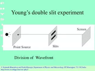
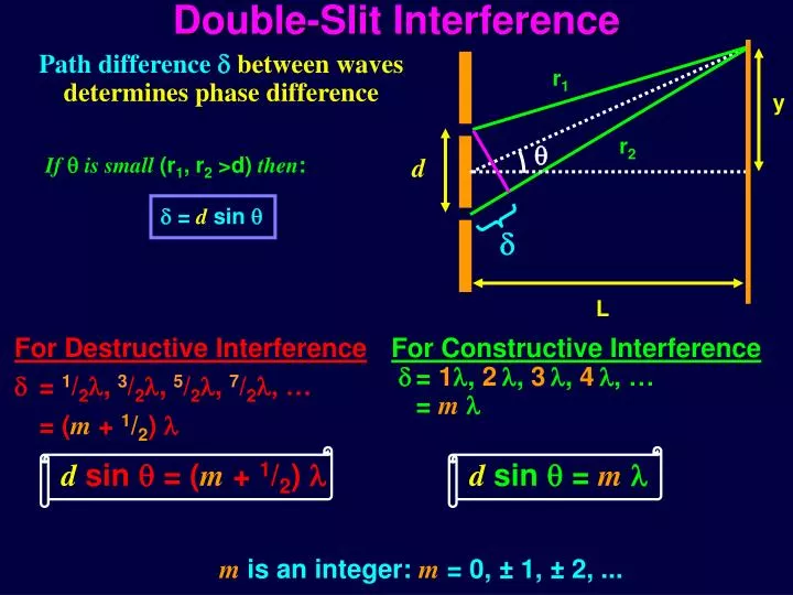
Double-Slit Interference. r 1. y. r 2. . d. . L. For Destructive Interference = 1 / 2 , 3 / 2 , 5 / 2 , 7 / 2 , … = ( m + 1 / 2 ) . For Constructive Interference = 1 , 2 , 3 , 4 , … = m . d sin = ( m + 1 / 2 ) . d sin = m .

E N D
Double-Slit Interference r1 y r2 d L For Destructive Interference = 1/2, 3/2,5/2, 7/2, … = (m + 1/2) For Constructive Interference = 1, 2, 3, 4, … = m d sin = (m + 1/2) d sin = m Path differencebetween waves determines phase difference Ifis small (r1, r2 >d) then: = d sin mis an integer: m = 0, ± 1, ± 2, ...
Exposed to Neon laser light passing uninterrupted through a narrow pair of slits, point P is the location of a bright fringe in the resulting interference pattern. P If a thin plate of clear crown glass held normal to the path to P covered one of the slits, the point P would • still be a point of constructive interference. • become a node (dark fringe) of destructive interference. • have a phase difference between the two slits that • depended on the thickness of the plate.
Exposed to Neon laser light passing uninterrupted through a narrow pair of slits, point P is the location of a bright fringe in the resulting interference pattern. P If a thin sheet of clear crown glass precision ground exactly to a thickness equal to an odd number of wavelengths N is held normal to the path to P covered one of the slits, the point P would nglass=1.5 • still be a point of constructive interference. • become a node (dark fringe) of destructive interference. • have a phase difference between the two slits that • depended on the thickness of the plate.
Another way to get Interference • Thin oil film on water: • Part of the incoming light is reflected off the top surface (point A), part at the lower surface (point B). • Light traveling through oil travels extra distance (from A to B to C). • If this distance is l, 2l, 3l, 4l, … • constructive interference! • If this distance is l/2, 3/2l, 5/2l, … • destructive interference! Note:herenair<noil<nwaterguarantees E/B fields invert upon reflection at both interfaces, so that only the difference in pathlength is important.
A glass (n=1.60) lens is coated with a thin film of fluoride (MgF2, n=1.38). What minimum film thickness makes =550nm light non-reflecting? Is the condition for destructive interference between the reflected rays of light. The minimum thickness, t, would be for m = 0.
A glass (n=1.60) lens is coated with a thin film of fluoride (MgF2, n=1.38). What minimum film thickness makes =550nm light non-reflecting? t=/4 180o phase change for each reflection
p = Sobject f > 0 for converging optics q = Simage f < 0 for diverging optics • For a converging lens if p>f then • q is always positive (real image). • q is always negative (virtual image). • q could be positive or negative. • q is zero.
p = Sobject f > 0 for converging optics q = Simage f < 0 for diverging optics • For a converging lens if 0<p<f then • q is always positive (real image). • q is always negative (virtual image). • q could be positive or negative. • q is zero.
p = Sobject f > 0 for converging optics q = Simage f < 0 for diverging optics • For a converging lens if p0 then • q is always positive (real image). • q is always negative (virtual image). • q could be positive or negative. • q is zero.
p = Sobject f > 0 for converging optics q = Simage f < 0 for diverging optics • For a converging lens if p<0(virtual object) • then • q is always positive (real image). • q is always negative (virtual image). • q could be positive or negative. • q is zero.
p = Sobject f > 0 for converging optics q = Simage f < 0 for diverging optics • For a diverging lens if p>0(real object) then • q is always positive (real image). • q is always negative (virtual image). • q could be positive or negative. • q is zero.
p = Sobject f > 0 for converging optics q = Simage f < 0 for diverging optics • For a diverging lens if p<0(virtual object) • within the focal length, | p |<| f |, then • q is always positive (real image). • q is always negative (virtual image). • q could be positive or negative. • q is zero.
p = Sobject f > 0 for converging optics q = Simage f < 0 for diverging optics • For a diverging lens if p<0(virtual object) • but outside the focal length, | p |>| f |, then • q is always positive (real image). • q is always negative (virtual image). • q could be positive or negative. • q is zero.
Answers to multiple choice conceptual questions. (3)have a phase difference that depends on the thickness of the plate. Within the glass, wavelengths of light are shortened: n = /n. So the introduction of the glass plate changes the total number of waves in the path from the lower slit to P. Exactly how many wavelengths (and whether it is even exactly a whole number of wavelengths depends on the glass’ thickness. • become a node (dark fringe) of destructive interference. With no glass plate, N=t/ wavelengths fill the air space where the glass would have been. Within the glass, Nglass = t/n = ng(t/). That’s ngN = 1.5N waves compared to N. That makes point P effectively 0.5N wavelengths further from the lower slit when the glass is in place. That’s an added 0.5N phase difference.
More answers to multiple choice conceptual questions. For a converging lens if p>f then (1) q is always positive (real image). Since fp is positive, and p-f is positive. For a converging lens if 0<p<f then (2) q is always negative (virtual image). Since fp is positive, and p-f is negative. For a converging lens if p0 then (4) q is zero. For a converging lens if p<0(virtual object) (1) q is always positive (real image). Makes fp negative, with p-f a negative number made more negative by subtracting f! For a diverging lens if p>0(real object) then (2) q is always negative (virtual image). For a diverging lens if p<0(virtual object) but outside the focal length, | p |>| f | (2) q is always negative (virtual image). With both f and p negative, fp is now positive, and p-f is the difference between 2 negative numbers.If |p|>|f| the denominator is negative! For a diverging lens if p<0(virtual object) but outside the focal length, | p |>| f |, (1) q is always positive (real image). Again fp is positive, but now p-f is positive!