Download
1 / 46
460 likes | 587 Views
The use of the GDT based neutron source as driver in a sub-critical burner of minor actinides K. Noack Research Center Rossendorf (Germany). Budker Institute of Nuclear Physics, September 26, 2006, Novosibirsk, Russia. Content Part I: Transmutation of nuclear waste –

E N D
The use of the GDT based neutron source as driver in a sub-critical burner of minor actinides K. Noack Research Center Rossendorf (Germany) Budker Institute of Nuclear Physics, September 26, 2006, Novosibirsk, Russia
Content Part I: Transmutation of nuclear waste – a short overview on the actual state Part II: The GDT as neutron source in a sub-critical system for transmutation? (~ Presentation at OS`2006, Tsukuba, Japan)
To become a long-term sustainable option for the worlds energy supply fission reactor technology must: • maximally use nuclear fuel (uranium) and • minimize its high level waste (HLW)!
3-4 years Uranium Burn-up Spent nuclear fuel U-235: 3-5% U-238: 95-97% • U: 95.5% • + TRU isotopes • Pu: 0.9% • MA • (Np, Am, Cm): 0.1% • + Rad. FP isotopes: 0.4% • + Stable isotopes: 3.2% Problem on short-time scale. Main problem on long-time scale. HLW repository problem ! Goal: To transmute radio-isotopes in short-lived or stable isotopes by neutron reactions! # In today´s Light Water Reactors (LWRs): 1 LWR (~1.3 GWel.) produces per year (kg): Pu: ~ 270 Am: ~ 13.5 Np: ~ 13 Cm: ~ 2 FPs: ~ 1000 :Partitioning & Transmutation France, Japan, USA
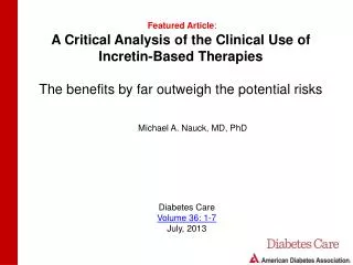
Classic glass MA + FP Pu + MA + FP FP Light glass (B. Frois) # Radiotoxicity for various options of waste disposal:
From: M. Salvatores, FZR-presentation (2005) Pu & decay products MAs & decay products >105 years ~104 years FPs ~3x10² years Total Radiotoxicity Uranium ore Tc-99, I-129 102 103 104 105 106 Years after discharge
From: M. Salvatores, FZR-presentation (2005) Partitioning & Transmutation (TRUs and FPs) Geological Disposal Partitioning FP Pu MA FP Transmutation Partitioning Dedicated Fuel Reprocessing Dedicated Fuel Fabrication Pu, MA # Partitioning & Transmutation of TRUs and FPs: Geological Disposal Direct Disposal Spent Fuel from LWRs
Capture Fission • : Only low transmutation rates of FPs achievable! M. Salvatores: The problem is not yet solved! # Neutron reactions for transmutation: • Minor actinides are fissionable! • Fission is the preferable reaction for transmuting MAs : - substantially shorter life-times, - possibility of „fast systems”. • „Fast“ neutrons with En > 0.5 MeV are necessary. • Is the only option for FPs. • However: secondary nuclei can be also long-lived. • Thermal or intermediate (En:~ eV-10 keV) neutrons are necessary. • : „Fast systems” should be a suitable tool for transmuting MAs!
„Driven sub-critical system“ „Fast reactor“ • Main class: ADS = Accelerator Driven System : What is the most important physical difference ? & What is the advantage of an ADS compared to FR ? # An efficient burning of Pu and MA isotopes demands: • A „fast system“ with high neutron flux inside an acceptable large volume! • Fission Technology offers two options:
A minimum on fission reactor physics: • # Neutron field in a reactor: • Solution of the Static Reactor Equation = eigenvalue equation • Neutron field power distribution in the reactor • Eigenvalue = keff - “effective multiplication factor” • > 1 - super-critical reactor, P: • keff = 1 - critical reactor, P: • < 1 - sub-critical reactor P: • Important phenomenon: • „Delayed“ fission neutrons with a relative portion: eff6.5x10-3 ! • It makes possible to control a fission reactor !
: T 0.01 - 0.1 s !!! „prompt“ super-critical state What is the impact of a power increase on keff ? (“reactivity effects”) super-critical state 1+eff1.0065 : T 100 s ! eff ? „delayed“ super-critical state 10-3 critical state constant power sub-critical state „driven sub-critical systems“ ~0.95 keff 1.0 0.99 0.98
Reactor safety considerations: • Fast reactors: • eff should be large! • Positive total reactivity effects (keff↗) should not appear! : What is the impact of MAs on these demands? • In Fast Reactors the maximum allowable fraction of MAs in the fuel is ~ 5 % only ! • Driven sub-critical systems: keff ≤ 0.98 ! • : „They offer much higher flexibility for burning Pu and MAs than Fast Reactors“ !
Waste Use of ADS Time 2050 2060 2030 2040 • Strategic role of Driven Sub-critical Sytems in the future of Nuclear (Fission) Energy in US M. Cappiello, „The potential role of Accelerator Driven Systems in the US“, ICRS-10 (2004) : The use of the GDT neutron source as driver in a Driven System for transmutation of nuclear waste could be an additional goal for further Research & Development !
# Effect of MA introduction on reactivity coefficients in a Na-cooled Fast Reactor: Variation (%) 20 Increase of Na-void effect ! A 10 Decrease of eff ! 0 Decrease of Doppler effect ! D B C - 10 Good effect: D Decrease of burn-up - 20 C - 30 B - 40 Act. Mineurs Chargés (%) - 50 0 2 4 6 8 10 From: M. Salvatores, FZR-presentation (2005) Bad effects by MAs: A: Na-void effect (keff↗) B: Doppler-effect (keff↘) C:Burn-up D: eff
THE GDT AS NEUTRON SOURCE IN A SUB-CRITICAL SYSTEM FOR TRANSMUTATION? K. Noack Research Center Rossendorf (Germany) A. Rogov Joint Institute of Nuclear Research Dubna (Russia) A.A. Ivanov, E.P. Kruglyakov Budker Institute of Nuclear Physics Novosibirsk (Russia) (With modifications for BINP-presentation) Open Systems´2006, July 17-21, 2006, Tsukuba, Japan
Introduction (1/3) 3-4 years Uranium Burn-up Spent nuclear fuel U-235: 3-5% U-238: 95-97% • U: 95.5% • + TRU isotopes • Pu: 0.9% • MA • (Np, Am, Cm): 0.1% • + Rad. FP isotopes: 0.4% • + Stable isotopes: 3.2% Main problem on long time scale. HLW repository problem ! Goal: To transmutate radio-isotopes in short-lived or stable isotopes by neutron reactions. 2 • Fission reactor technology must • recycle spent nuclear fuel and • minimize its high level waste (HLW) ! :Partitioning & Transmutation ! Japan (JAEA): „OMEGA“
Classic glass MA + FP Pu + MA + FP FP Light glass (B. Frois)
„ADS“ : # Suitability of the GDT n-source for a driven system? # How does it compare with the ADS? Introduction (2/3) 3 • Two efficient ways for transmutation of TRU´s by neutron reactions: 1) Fast reactors (“effective multiplication factor”: keff=1) 2) Sub-critical systems (keff=0.95-0.98) that are driven by an “outer” neutron source • Advantage: More flexibility because of less stringent safety requirements ! • Requirement: Powerful neutron source ! • „Accelerator Driven Systems“ (ADS) • Spallation neutron source
Introduction (3/3) 4 • The idea of a GDT-DS for transmutation: GDT experimental device (BINP, Novosibirsk)
Pn0.25 MW Factor ~ 1.8 The Neutron Sources 5 • Comparison of near-term projects: ADS GDT (“basic variant”) 1) Total intensities p-beam: 1 GeV x 10 mA = 10 MW Yn = 20 n/p (at Pb) : SADS = 12.5x10¹⁷ n/s n-power: Pn=1.56 MW DT fusion neutrons SGDT=6.9x10¹⁷ n/s # SNS (ORNL): 1 GeV x 1.4 mA, 60 Hz pulsed, 28.04.2006 – first neutrons ! 2) Energetic efficiencies PAccel. = 20 MWel PNBI = 60 MWel (!) price [W/(n/s)]:pADS = 1.6x10⁻¹¹pGDT = 8.7x10⁻¹¹ (!) Factor ~ 5 ! # Peculiarity of the GDT-source: SGDT = 2 x (1/2) !
# Spallation reaction: neutron yield per proton (Pb, Pb/Bi): K. van der Meer et al., Nucl. Instr. and Meth. in Phys. Res. B 217 (2004) 202-220
: Pinp= (el. Power) (From Yu. Tsidulko) Power losses should be reduced or recovered! : Pn=
p 200 Reflector Void 150 Height z (cm) 120 Core 32% , 68%!!! Target • Dedicated core:Pu & MA Fe, Pb-Bi • Coolant: Pb-Bi eutectic • Reflector: Steel, Pb-Bi • Target: Pb-Bi • Buffer: Pb-Bi 50 Buffer 0 0 20 10 142 92 Radius r (cm) Calculation Models (1/2) 6 # ADS principles # OECD-NEA Calculation Benchmark (1999) for an accelerator-driven MA-burner with nominal power = 377 MW. (Developed from ALMR/PRISM) # Features
Calculation Models (2/2) B C z z r r „ADS“ „GDT-DS“ „GDT-DS+B“ Radius: 10 cm Height: 50 cm Spallation source DT fusion source – cylinder: „MIXED“ Spallation spectrum in„GDT-DS“ 7 # Geometric systems: A z r # “External” neutron sources:
Two types of transport calculations: • Reactor criticality calculation (without external source) keff • With external sources • Tools: • Neutron transport code: MCNP-4C2 • Nuclear data from: JENDL-3.3 (NDC of JAEA) Neutron Transport Calculations (1/5) 8
B Effective multiplicity: Meff=keff/(1-keff) z r # 0.95<keff< 0.96 ! (1999) # Positive feature of 14 MeV neutrons: High probability of n,2n reactions at Pb and Bi ! But: No effect at Na ! Neutron Transport Calculations (2/5) 9 • Calculated integral parameters (per source neutron): Spall. Sp. 17.5 1070 0.065
total n,2n n,3n n, 10 MeV
Neutron Transport Calculations (3/5) 10 • Flux distributions (per source neutron): Total Flux: Radial dependence in core
Neutron Transport Calculations (4/5) 11 • Flux distributions (per source neutron): Power peak factor over height at r=21 cm
Neutron Transport Calculations (5/5) 12 • Flux distributions (per source neutron): Spectra of energy group fluxes at r=21 cm
x ~1.5! ! 2.5~ x Today: 0.96 <keff<0.98 ! The MA-burners (1/2) 13 • Calculated integral parameters: keff: 0.95817 0.95008 0.95856 Q=5.2 Q=2 * One MA-burner on each side !
The MA-burners (2/2) 14 • Radial flux distribution (at nominal power):
T-breeding module Tritium breeding 14a # T-breeding module: • ITER inboard module, • He cooled pebble bed (Be and breeder pebble beds, breeder: Li4SiO4 with 40% Li-6) • FZKA 6763 (FZ Karlsruhe, 2003) • 6Li + n 4He + 3H + 4.8 MeV • Result: 355.3 g tritium / f.p. year ! („basic variant“, sum of both sides)
Conclusions (1/2) 15 (1) Energetic price of the neutron emission intensities: pGDT 5 x pADS !!! (2) ADS and GDT neutron source projects do not supply sufficiently high source intensities to operate the MA- burner at nominal power. For that are necessary: SADS: x ~1.5 SGDT: x ~2.5(for 2 burners !) (3) Alternatively, one has to redesign the MA-burner so that for ADS: keff 0.97 for GDT: keff 0.98. !!! (4) Fusion source neutrons generate a substantially higher fission power in the core by n,2n reactions at the nuclei of the Pb-Bi coolant!
Conclusions (2/2) 16 (5) The power multiplication factor Q of the driven MA- burners: QADS 2.6 x QGDT-DS ! (6) For the same power of the driven MA-burners one can expect: [MA-burning rate]ADS [MA-burning rate]GDT-DS
1) Energetic efficiency must be increased! # The Q-factor must be comparable with that of ADS! # Increase of Te is the key issue: Te = 0.75 keV Te 2.25 keV ! ~60% • As goal for the GDT neutron source project: 2) „Next Step“ with a modified MA-burner: Project „π“ # MA-burner*: k*eff=0.98, P*th=500 MW GDT-NS*: S*=10.8x10¹⁷ n/s (P*n=2.5 MW) instead of: S= 6.9x10¹⁷ n/s (Pn=1.56 MW) by: Te=0.75 keV T*e1.25 keV !
Diagram from Yu. Tsidulko 5.2 2 x 377-MW-burners 2 x 500-MW-burners*, k*eff=0.98 3.14 „Basic variant“ + 2 burners 2 ~2.25 0.75 ~1.25 # Pinj=60 MW (el.), Einj=65 keV Q P=
~60% • As goal for the GDT neutron source project: 1) Source strength (neutron power): # MA-burner: keff=0.98, Pth=500 MW GDT-NS: S=10.8x10¹⁷ n/s (Pn=2.5 MW) instead of: S= 6.9x10¹⁷ n/s (Pn=1.56 MW) 2) Energetic efficiency: # The Q-factor must be comparable with that of ADS! # Increase of the electron temperature is the key issue: Te=0.75 keV Te=2.25 keV !
R. Klapisch, Europhysics News, Vol. 31 No. 6 (2000); (Proposed by C. Rubbia) # Transmutation of 99Tc using neutron capture: „Adiabatic resonance crossing“
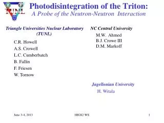
From: G. Alberti et al., NSE 146, 13-50 (2004) „Fast systems“ Fast Neutron spectrum [104<--------->4x10⁶] # Flux spectra of the MA-burner and of FR PHENIX: (Na cooled)
#σc and σfis for important TRUs: From: D. Westlen, RIT Stockholm (2001) FR FR FR FR E (eV) 104 105 106 107 : At high neutron energies (En>0.5 MeV) fission dominates over capture !
Originally from C. Rubbia # Advantage of fast neutron spectra for MA-burning: α – probability of capture
„Energy amplifier“ proposed by C. Rubbia (1993): Release of nuclear energy Transmutation of nuclear waste ! # Principles of an ADS: •Accelerator ↓ particle beam ↓ • Target ↓ neutrons ↓ • Sub-critical system (arrangement of nuclear fuel) ↓ Strong neutron field inside the whole volume of the fuel system by means of fissions ! (protons) (heavy metal) (spallation)
# Schematic view of a lead- cooled Fast Reactor (pool-type): • Is one of 3 Fast Reactors among 6 reactor types considered in the GENERATION IV - • International - Forum. • Core without external neutron source • Power control by absorber rods