Download
1 / 19
200 likes | 397 Views
Behavioral Modelling - 1. Verilog Behavioral Modelling. Behavioral Models represent functionality of the digital hardware. It describes how the circuit will operate without specifying hardware. There are two important keywords for behavioral description.

E N D
Verilog Behavioral Modelling Behavioral Models represent functionality of the digital hardware. It describes how the circuit will operate without specifying hardware. There are two important keywords for behavioral description. initialSpecifies a single-pass behavior. always Specifies cyclic behavior.
Behavioral Modelling initialkeyword is followed by a single statement or a begin…endblock The statement following initial is executed once at t=0 and it expires. alwayskeyword is followed by a single statement or a begin…endblock The statement following alwaysis executed repeatedly until simulation is stopped.
Use of initial and always. Defines a clock with 20 unit clock period.
always and event control @ always @(event control expression) begin ....... end @ is called event control operator. always @(event) waits until the event occurs. When event takes place begin.. end block will be executed. Example: wait for positive edge of clock always @(posedgeclock) always @(posedgeclock or negedgereset)
Multiple statements in always block always @ (A or B or C or OUT2) /* Note: OUT2 is output of one statement but input of another statement */ begin OUT1 = (A&B) | (B&C) | (C&A) ; OUT2 = {A,B,C}; OUT3 = OUT2 >>> 2; OUT4 = OUT2 << 1; /* inside the always block all instructions are executed sequentially, like in programming languages (exceptions will be mentioned later) */ end
Multiple always blocks always @ (A or B or C) OUT1 = (A&B) | (B&C) | (C&A); always @ (A, B, C) OUT2 = {A, B, C}; always @ (*) OUT3 = OUT2 >> 1; /* All the three always blocks will run concurrently i.e. all the LHS of each of the always blocks will be calculated at the same instant of time */
Procedural Blocks module MultiplexerD (input a, b, s, output w); reg w; always @(a, b, s) begin if (s) w = b; else w = a; end endmodule always statement Sensitivity list Can be used when the operation of a unit is too complex to be described by Boolean or conditional expressions if-else statement
Blocking and non blocking assignments There are two types of assignments in verilog. In blocking assignment the instuctions are executed sequentially one after the other. In non blocking the left hand side is assigned the value of the right hand side simultaneously at the end of the simulation timestep. These statements are executed in parallel.
Blocking and Nonblocking assignment examples • Blocking assignment: Evaluation and assignment are immediate always @ ( a or b or c) begin x = a | b; //Evaluate a|b and assign value to x y = a ^ b ^ c; // Evaluate a^b^c and assign value to y z = b & ~c; //Evaluate b & ~c and assign value to z end • Non Blocking assignment: Assignments deferred until right hand side has been evaluated (assigned at the end of timestep) always @ (a or b or c) begin x <= a | b; //Evaluate a|b but defer assignment of x y <= a ^ b ^ c; // Evaluate a^b^c but defer assignment of y z <= b & ~c; // Evaluate b & ~c but defer assignment of z end
Blocking vs. Nonblocking If A=3 and B=5 B=A ; C=B+2 ....... will set B=3 and C=5 B<=A ; C<=B+2 …… will result B=3 and C=7
Blocking and non blocking assignments Swap Operation • Blocking always @ (*) begin temp = b; b=a; a=temp; end • Non blocking always @ (*) begin a<=b; b<=a; end
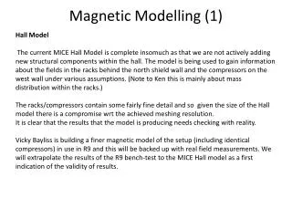
Blocking and non blocking assignment examples module blocking (in, clk, out); input in, clk; output out; reg out, q1, q2; always @ (posedgeclk) begin q1 = in; q2 = q1; out = q2; end endmodule module nonblocking(in, clk, out); input in, clk, out; output out; reg q1, q2, out; always @ (posedge clk) begin q1 <= in; q2 <= q1; out <= q2; end endmodule
Circuits which the above code is synthesized to Non Blocking Assignment Blocking Assignment
Rule of thumb You represent all your combinational logic by blocking assignment. You represent all your sequential logic by non-blocking assignment
Flip-Flop Flip-Flops are used in data part for flags and data storage A Software-Like Procedural Coding Style `timescale 1ns/100ps moduleFlop (reset, din, clk, qout); input reset, din, clk; outputqout; regqout; always @(negedgeclk) begin if(reset) qout<= 1'b0; elseqout<= din; end endmodule Synchronous reset input Flip-Flop triggers on the falling edge of clk Input The Body of always statement is executed at the negative edge of the clk signal A Signal declared as a regto be capable of holding its values between clock edges A Non-blocking Assignment
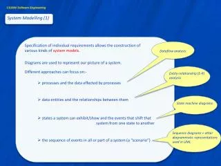
D flip-flop with active-low asynchronous reset • Behaviour of the circuit • reset_n is active low signal which clears output when low • Q and Q_n are complimentary outputs of the flip flop • On the positive edge of the clock the input D is passed on to the output Q. D Q Q_n clk reset_n
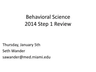
D flip-flop with active-low asynchronous reset always @ (posedgeclk or negedgereset_n) begin end if(reset_n == 0) begin Q <= 0; Q_n<=1; end else begin Q <= D; Q_n <= !D; end