Download
1 / 25
250 likes | 397 Views
Aims. Provide detailed information to allow the distribution of permeability to be evaluated.Define the most likely fluid flow model for the outcropTo demonstrate that GetRichQuick will not get rich, quickly or otherwise. Methods for data collection. Sub-team 1

E N D
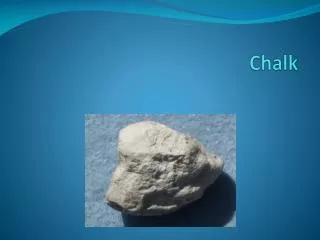
1. Flamborough Chalk Outcrops DrillItOrDie Plc.
2. Aims Provide detailed information to allow the distribution of permeability to be evaluated.
Define the most likely fluid flow model for the outcrop
To demonstrate that GetRichQuick will not get rich, quickly or otherwise
3. Methods for data collection Sub-team 1 � jointing
Fracture frequency for individual beds
Fracture orientations
Vertical connectivity of the fracture systems:
In plan
In section
4. Methods for data collection Sub-team 2 � faulting and fracturing
Frequency of faults versus throw
Clustering of faults
Impact of faults � retard or enhancement of flow
Fault timing relationship with joints
5. Jointing
6. Interpretation In section the joints and fractures are spatially dependant on the thickness of the bed
Thicker beds have more distance between fractures and lower fracture density
The fractures in thicker beds tend to continue through the surrounding thinner beds
7. Vertical connectivity Thinner beds are typically bound by clay rich layers above and below
Stylolites present in thick beds and are laterally extensive prohibiting vertical permeability
Governed by larger joints through thick and thin beds
8. Stylolites
14. From fracture plan analysis�
Near 100% connectivity in all chalk beds
20cm thick units have an 4x greater degree of fracturing as those measuring 30cm
Dominant fracture orientation ~125�(+/-10�), sub-parallel to faults
Fracture density increases around fault planes
15. Impact on fracture permeability Lateral fluid flow better in thinner chalk beds, but still active in thicker units
General preferential orientation to fluid flow in SE-NW direction (fault controlled)
Vertical fluid flow determined by fracture permeability of thicker units as smaller fractures (apparent in thin beds) do not translate
16. Implications for Reservoir Model Fracture analysis has shown that fluid flow will be dominantly horizontal in thinner beds which are heavily fractured
Degree of vertical flow is controlled by larger joints that propagate through beds of various thickness
Fractures and joints play a major role in the permeability of the chalk
To maximise production:
Fluid flow will produce a higher yield laterally rather than vertically
Possible horizontal drilling may maximise flow out of reservoir
18. Short offset faults
19. Longer Offset Fault
20. Large Offset Fault, example of fault gouge & a damage zone
21. Fault Morphology Two main fault trends W-E & ENE-WSW
The amount of offset determines the likely role of the faults as fluid conduits or barriers.
Short offset faults contain highly permeable fault bend zones. This suggests a refraction style of growth, this being the case the position of fault bends is determined by competency of the unit which it propagates through so that:
Clay layers & less competent chalk layers are more likely to result in fault bends concentrating fractures & flow
Thinner layers (more fractures) are less competent and may cause minor fault bends
22. Characteristics of small offset faults
23. Effects of Offset The large offset faults appear are likely to act as barriers unless their damage zones contain open zones i.e vugs that could concentrate flow through the fault gouge, however the extensive damage zone would likely form a barrier to flow over a production timescale
Short offset faults increase permeability although there needs to be further research carried out into all the factors that determine clay smear along the faults
24. Incorporation of fault data into a reservoir model Definition of seismic scale faults & there spatial extent will allow for potential compartments to be identified.
To maximise production
Drill through sealing compartmentalising faults
Utilise the dominant trend of intra reservoir small scale faults to maximise production
25. Limitations of Flamborough as an Analogue Uplift and erosion may affect the structural features recorded i.e the width of fractures could be significantly less, reducing permeability
26. Conclusions Large joints/fractures and faults determine level of vertical connectivity
The majority of permeability is distributed horizontally
We believe that the data collected and models proposed give us the best understanding to analysis the suitability of the outcrop as a reservoir