Download
1 / 33
330 likes | 373 Views
XTOD Diagnostics. Photon Systems Breakout Lehman Review July 11, 2007. LCLS Layout. FEE (Front-End-Enclosure) Diagnostics SOMS HOMS. Linac. Undulator Hall. X-Ray Tunnel. FEH (Far Experimental Hall). NEH (Near Experimental Hall).

E N D
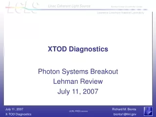
XTOD Diagnostics Photon Systems Breakout Lehman Review July 11, 2007
LCLS Layout FEE (Front-End-Enclosure) Diagnostics SOMS HOMS Linac Undulator Hall X-Ray Tunnel FEH (Far Experimental Hall) NEH (Near Experimental Hall)
XTOD Commissioning Diagnostics and Offset Mirrors in the Front End Enclosure (FEE) Wall penetration K Spectrometer Indirect Imager Solid Attenuators Slit Collimators Wall penetration Thermal Sensor Fixed Mask Gas Attenuator Gas Detector Beam Direction Gas Detector Direct Imager (Scintillator) FEL Offset Mirror Systems
XTOD Optics and Diagnostics in FEE 5 mm diameter collimators Soft X-Ray Offset mirror system Gas Detector Hard x-ray Monochrometer (K Spectrometer) Direct Imager Solid Attenuator NFOV Slit Hard X-Ray Offset mirror system Total Energy Thermal Detector Indirect Imager e- Gas Attenuator WFOV Gas Detector Start of Experimental Hutches Muon Shield
Attenuator on order N2 boil-off (surface) Gas detector Flow restrictor 4.5 meter long, high pressure N2 section Differential pumping sections separated by 3 mm apertures 3 mm diameter holes in B4C disks allow 880 mm (FWHM), 827 eV FEL to pass unobstructed Solid attenuators N2 Gas inlet Green line carries exhaust to surface Gas detector
Gas detectors share differential pumping with the Gas Attenuator PMT Electronics Bandpass Filter Photo Multiplier Tube Al liner 3 mm apertures along beam path Differential Pumping Section Magnet Coils Cylindrical Vessel Beam / Gas Interaction Region (~0.1 – 2 Torr N2) Magnet Power Supply and Controller APD Gas Feed And Pressure Control LCLS X rays cause N2 molecules to fluoresce in the near UV
Gas detector SSRL prototype Port for pumping Photo Multiplier Tube Magnet Coils Be window Gas Feed And Pressure Control Avalanche Photodiode Port for LED illuminator and florescence samples
Prototype Gas Detector insert for measuring x ray induced photoemission of candidate wall materials
Gas Detector signal vs. magnetic field at various pressures Simulated Measured
Results of SSRL Gas Experiments: Comparison Model and Experiments (2X correction of calculated signal) We suspect that discrepancy at lower pressures is due to photo electrons (and secondaries?) hitting the chamber ends
Measured luminescence of solids at 8 keV Al UV signal closely represented by 9:00, B on (red): Al is the best
Time dependence of gas detector signal from the 8keV fundamental
Indirect imager finds spontaneous core Raw soft spontaneous After reflection Princeton Instruments backilluminated CCD camera 25 x 25 mm chip, 20 um pixel size ML mirror 0.1% reflectivity, 1% bandwidth Status Indirect Imager: PRD in progress Vacuum chamber
Channel-cut Si Monochrometer will be used to measure relative K of two undulator segments Two undulator spontaneous spectrum. Falloff of high energy tail is independent of aperture Monochrometer Detector Detector monochrometer measures intensity at a single point Linac E variation and measurement Use linac E variation and measurement to obtain other points along curve Two undulator spontaneous high energy falloff has highest slope when DK/K=0. Status K Spectrometer: PRD in progress
5 Tc200 Tc150 Tc100 4 3 2 1 0 0 0.05 0.1 0.15 0.2 0.25 0.3 Time [ms] Total Energy (Thermal) Sensor provides calibrated measurement of FEL pulse energy Measures FEL energy deposition through temperature rise Cu heat sink Thermistors Nd0.66Sr0.33MnO3 (On back of substrate) Sensor Temperature Rise FEL pulse [K] 0.5 mm Si substrate t = 0 t = 0.25 ms t = 0.1 ms Thermal diffusion of FEL energy Status Thermal Sensor: PRD done SCR done PDR done Prototype done FDR in progress
Thermal sensor prototype Pulse tube cooler Optics for measuring, focusing, and steering laser beam 532 nm laser Sensor cryostat
Thermal sensor signal at 1mJ 0 volt bias 2 volt bias V1 V1 Vbias Rsensor R1 V1 V2 R3 R4 V2 V2
Channel 1 pulse at 400 uJ with 2V bias Subtract value at -100us Sample voltages at particular times, convert to DRcmr then to DT
Total energy prototype measured and predicted signal Finite difference prediction DT, °K DT, °K Measured data Absorbed Laser Energy, mJ Absorbed Laser Energy, mJ At 100 msec At 3 msec
Thermal sensor, preliminary design Thermal Detector Calibration Laser Laser Energy Meter
Direct Imager 30 fps CCD Camera Scintillators on movable shaft ND filter wheel High resolution lens 4 Scintillators: Thin, stops 8 keV FEL find soft x-ray FEL Very thin, stops 826 eV FEL find soft x-ray FEL Thick, stops spontaneous spontaneous studies + one other for tests diamond Stops FEL Transmits spontaneous Photodiode for K measurement 30 fps CCD Camera Low resolution lens
Single shot measurement of f(x,y), x, y ,u Direct Imager, preliminary design Camera Status Direct Imager: PRD done SCR done Prototype done PDR done in Final Design Scintillators
Camera QE Scintillator emission spectrum
Soft X-Ray Spontaneous signal in WFOV Direct Imager Absorbed in 5 um YAG, Maximum ~ 20,000 photoelectrons/pixel Camera: Photometrics 512B Objective: Navitar Platinum 50 Power: 0.1365 NA: 0.060
Scintillator signals in FEL equivalents Needed x-ray attenuation Needed x-ray attenuation YAG Range Needed visible attenuation CCD Range Need x-ray attenuation of > 100 and visible attenuation of > 10
Prototype Direct Imager testing Enclosure Flat field testing of camera only CCD Integrating Sphere Camera Pulsed UV laser testing with YAG WFOV Optic UV beam splitter N2 Laser YAG Insertable photodiode ND filter Lens Photodiode
Photon Transfer Curve Our fit: Manufacturer:
Cascade 512B on-chip gain measurements Gain: 1 On-Chip: 0 to 4000, Exposure Time: 5 to 190 Lamps: 1, 2 Measured Gain = Slope g(j)/Slope g(0) On-Chip Gain Measured Gain Slope February 12, 2007 Run 12
Direct Imager image of N2 laser excited YAG scintillator at 20 Hz YAG excited by N2 laser Boundary of 10 mm dia. YAG disk
FEL Offset Mirror Systems have “Pop-in” imagers for alignment P P P P P P
Bidirectional Popup Viewer allows viewing of the x-ray beam and the collimator
We are studying expected signal levels in the Pop-in cameras Low Energy, All undulator modules 100% Spontaneous Propagated through fixed mask, pipes 12 Boron Carbide windows are open Slit is open No attenuation, no gas detector Photons absorbed in 1 mm YAG, Full Well: 200,000 # photoelectrons ~ 5660 per pixel Misses Mirror 1 Reflected off Mirror 1 SOMS Run005
Summary • Progress continues on XTOD diagnostics: • Procurement - Slit, Fixed Mask, Attenuator • PDR – Direct Imager, SOMS, Thermal Detector • SCR – K-Spectrometer • PRD – HOMS, Indirect Imager