Download
1 / 41
410 likes | 552 Views
Electrical Tapes & Optical Links. Electrical tapes Al/kapton tapes for SCT Wiggly tapes for SCT EC Lessons learned. Optical Links Survey reliability in ATLAS Focus on problematic systems Lessons learned and being learnt. Al/kapton Tapes. 50 um Al/50 um kapton

E N D
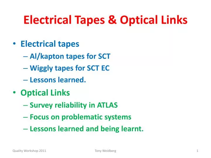
Electrical Tapes & Optical Links • Electrical tapes • Al/kapton tapes for SCT • Wiggly tapes for SCT EC • Lessons learned. • Optical Links • Survey reliability in ATLAS • Focus on problematic systems • Lessons learned and being learnt. Tony Weidberg
Al/kapton Tapes • 50 um Al/50 um kapton • 500 um wide tracks for HV & control signals (wider tracks for LV). • Al/kapton tape was quite robust but … • After Ni/Sn plating for soldering to PCBs tapes were extremely fragile photo next slide. • We believe this is due to hydrogen embrittlement. • Managed to do repairs(bodge) for barrel LMTs • Changed to Cu/kapton for EC because number of breaks unmanageable. Tony Weidberg
500 mm Cracks appear to form on grain boundaries Tony Weidberg
Cracks Barrel kapton flexes • Layout of opto-flexes not optimised because there were too many flavours to design! • Added ceramic stiffeners behind connectors. Crack! Tony Weidberg
EC Wiggly Tapes • Cu/kapton tapes for HV and control signals. • CCA twisted pair for LV. • Twisted pair attached to Cu/kapton photos. Tony Weidberg
Modulewith ASICs silicon Flex Circuits Redundancy links Opto-package with fibres Tony Weidberg
End Cap Flex Circuits CuKapton for HV and control signals CCA twisted pair for high current (DC power) Stiffener Tony Weidberg
Wiggly Tape Problems • First tapes made by Samtec with new photo-imageable cover layer bad idea, too fragile. • Even with conventional cover layer had many breaks on Cu/kapton. • Problem is CCA wires much stiffer than Cu/kapton caused breaks when tapes were bent (Cu/kapton alone was very robust). • Shouldn’t have tied CCA to Cu/kapton Tony Weidberg
Tapes: Lessons Learned • Test tapes in realistic routing during R&D not during production/detector integration. • Al/kapton tapes can be used in future but we should connect with wire bonding not soldering. Tony Weidberg
Optical Links • Summary VCSEL reliability in ATLAS • Failure rates & FITs • Systems with major problems • ATLAS LAr • SCT/Pixel TXs • SCT on-detector VCSELs • Lessons learned and being learnt. Tony Weidberg
VCSEL Reliability in ATLAS Tony Weidberg
Reliability • Some systems with commercial & hermetic components have seen no failures • eg RPCs have ~ 10M device operating hours Failure rates <~ 100 FIT (failures in 109 operating hours), consistent with manufacturer’s claims. • Other systems have seen problems, focus on more serious cases • LAr OTx • SCT/Pixel TX • SCT on-detector Tony Weidberg
Possible Causes (1) • ESD • VCSELs known to have very low ESD thresholds • ESD most common cause of field failures for VCSELs • Controlled low level ESD pulses can cause a decrease in spectral widths Tony Weidberg
Possible Causes (2) • Humidity (TO can should be hermetic but suspect some damage during assembly) • Deliberately opened TO can • Operation of VCSEL in lab environment with RH ~ 55% shows decrease in spectral width Tony Weidberg
ATLAS LAr • OSA revealed two populations Failed devices nearly all show narrow spectral widths Width (nm) Remaining devices with narrow widths removed during 2011 shutdown No failures seen since Serial number Tony Weidberg
Pixel & SCT TXs • End of life failures experienced after ~ 6 months • ESD suspected during assembly all devices replaced with greatly improved ESD precautions • Lifetimes improved but still << 10 years required for ATLAS operation Original production Improved ESD Precautions Tony Weidberg
Failure Analysis • Many techniques available • EBIC to localise damage in plan view • FIB to prepare sample for STEM. Tony Weidberg
EBIC comparison working & Failed channels TL VCSEL array Dead Working • All taken with same SEM settings: 10KV spot 5 (roughly same mag 4700X and 5000x) • Original Image LUTs stretched to accentuate EBIC changes across VCSELs • Only Ch 10 shows distinct EBIC minima (dark spots) within the emission region • Ch 06 & 08 show some inhomogeneity but no distinct minima • Small dark speckles are surface topography Analysis by EAG
STEM Unused ChannelTL VCSEL array after FIB cut Top DBR oxide MQW (active region) Bottom DBR Analysis by EAG
STEM Failed ChannelTL VCSEL array after FIB cut DBR Defects at edge of Oxide DBR active MQW region Oxide MQW Analysis by EAG
Used Working Channel Plan View SEM Dislocations starting to form on edge of aperture Analysis by EAG
Humidity Hypothesis • Single channel VCSELs usually packaged in hermetic TO cans • Very difficult to package arrays in hermetic packages • Reliability of first arrays in damp environments was poor (lifetimes ~ 100 hours at 85C/85% RH) • Electrolytic corrosion hypothesis: • Moisture depletes As in oxide layer excess Ga point defects which grow toward active area Tony Weidberg
RH and Lifetime Correlation • Use (accidental) fact that RH was different for some SCT crates • Weibull fits to failures Mean Time To Failure • Correlation with RH similar to that reported in literature Tony Weidberg
Accelerated Aging Tests Very short MTTF Epoxy only delays humidity entering VCSEL Tony Weidberg
Humidity Tests • 85/85 test is extreme, so how do we know that humidity is the main cause of death? • Use OSA to look at spectral narrowing for • TX VCSELs in dry N2 • TX VCSELs in lab RH air Tony Weidberg
Widths clearly decreasing Tony Weidberg
Open Questions • Why have none of these devices failed yet? • Is all the data compatible with humidity being the only cause of failure? • Try to fit all data to common accelerated aging model. • More lessons to be learnt here … Tony Weidberg
Widths ~ constant Tony Weidberg
Example Spectra • Air ~ 50% RH • Loss of higher order modes visible • Dry N2 • Higher order modes very similar Tony Weidberg
Pixel On-detector VCSEL • Same Truelight VCSEL array/MT package as for the SCT/Pixel off-detector arrays which are failing • But inside detector very low RH • Accelerated aging tests for Truelight arrays at low RH: no deaths for 24 channels, T=85C, I=10 mA , 2100 hours lower limit on lifetime = 49 years Optical Power (mW) Electrical disconnects Time (h) Tony Weidberg
SCT On-detector VCSELs • ~1% failures: “delayed infant mortalities” • Burn-in 3 days at 70C insufficient to remove infant mortalities (requires 120C according to TL). • Custom-packageincompatible with higher temperatures. • 4 failures during operation in 2011. • Suspect that these are random failures because lifetime testing after radiation for batch of 20 VCSELs gave good results. • Radiation testing on samples from all wafers but no lifetime testing maybe we have some bad wafers? Tony Weidberg
Other Quality Issues • Use of unbalanced codes for SCT & Pixels data links off-detector system much more complicated use balanced codes in future! • Temperature variations of on-detector VCSEL arrays not studied carefully before production (required heaters). • Common series resistance for VCSEL connection. • Fibre management not always very good (eg SCT fibres violated minimum bend radius). Tony Weidberg
Redundancy vs Reliability • Redundancy only protects against random failures not end of life (as seen in SCT/Pixel TXs). • Only argument for redundancy is if entire detector will fail if one element fails. • Better to invest in quality and reliability a la CMS (0.04% dead (broken fibres) in 40,000 links) than redundancy. Tony Weidberg
Summary Optical Links Quality • Very reliable VCSELs are available commercially. • Reliability can be destroyed by many environmental factors • Wafer dicing and handling • Wire bonding • ESD/EoS • Humidity • Big advantage in using a commercial package: • Large manufacturers have performed extensive developments and reliability studies involving millions of device operating hours. • Commercial packages are “qualified by the customers” • If a commercial package can’t be used inside the ID then best option is minimal modification of a commercial component • Used successfully by CMS • Approach used by VL. Tony Weidberg
Backup Slides Tony Weidberg
Solutions for Humidity Problems • Some manufacturers claim to make VCSELs that are reliable in high RH • Details commercially sensitive but principle measure is blocking holes used for steam to grow oxide layer with a dielectric layer • AOC and ULM have made VCSELs that pass 1000 hours of 85C/85% RH should be ok for 10 years operation in normal lab environment
Reliability Tests • Bare AOC arrays • I=8 mA DC, 85C/85% RH • No deaths for 31 channels after 3200 hours • AOC arrays packaged by CSIST • I=10mA DC, 70C/85% RH, 60 channels used • No significant change in spectral widths for 2000 hours Initial increase when T increased from 20C to 70C
iFlame • Semi-hermetic package • Small form-factor compatible with ATLAS SCT/Pixel TX PCBs • Uses ULM (ViS) VCSEL which also passes 1000 hours of 85C/85% RH • We will repeat lifetime tests with OSA 4 channel TRx ATLAS 12x in production
Testing Static: LIV and RIN Dynamic test as full module TOSA ROSA Dynamic: BER-> Sensitivity Radiation tolerance test: Jan Troska et al. “Single-Event Upset testing of the Versatile Transceiver ” See poster #133 Versatile Transceiver - Development Status
VTrx Prototype TOSA Static: LIV and RIN Dynamic test as full module ROSA Dynamic: BER-> Sensitivity Radiation tolerance test: Jan Troska et al. “Single-Event Upset testing of the Versatile Transceiver ” See poster #133 Versatile Transceiver - Development Status
Successes • Silicon p-i-n diodes have turned out to be very reliable (no confirmed failures). • Fibres: no indication for fibre reliability problems even when minimum fibre bend radius violated. Tony Weidberg