Download
1 / 64
1.51k likes | 2.25k Views
Permanent Magnet Brushless DC Motor. Pros and Cons of Brushed DC Motor. Brushed Motor Pros Two wire control Replaceable brushes for extended life Low cost of construction Simple and inexpensive control No controller is required for fixed speeds

E N D
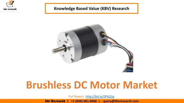
Permanent Magnet Brushless DC Motor Special Electrical Machines, Anuradha Publications
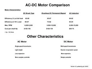
Pros and Cons of Brushed DC Motor • Brushed Motor Pros • Two wire control • Replaceable brushes for extended life • Low cost of construction • Simple and inexpensive control • No controller is required for fixed speeds • Operates in extreme environments due to lack of electronics • Brushed Motor Cons • Periodic maintenance is required • Speed/torque is moderately flat. At higher speeds, brush friction increases, thus reducing useful torque • Poor heat dissipation due to internal rotor construction • Brush Arcing will generate noise causing EMI Special Electrical Machines, Anuradha Publications
Brushed DC motors have been in commercial use since 1886. BLDC motors, however have only been commercially possible since 1962. • Limitations of brushed DC motors overcome by BLDC motors include lower efficiency and susceptibility of the commutator assembly to mechanical wear and consequent need for servicing, at the cost of potentially less rugged and more complex and expensive control electronics. • In the BLDC motor, the electromagnets do not move; instead, the permanent magnets rotate and the armature remains static. This gets around the problem of how to transfer current to a moving armature. In order to do this, the brush-system/commutator assembly is replaced by an electronic controller. The controller performs the same timed power distribution found in a brushed DC motor, but using a solid-state circuit rather than a commutator/brush system. Special Electrical Machines, Anuradha Publications
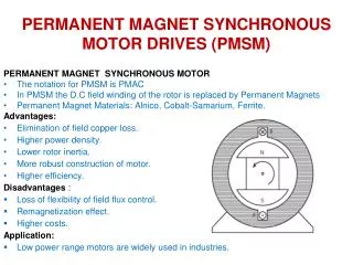
Pros and Cons of Brushless DC Motor • BLDC Motor Pros • Electronic commutation based on Hall position sensors • Less required maintenance due to absence of brushes • Speed/Torque- flat, enables operation at all speeds with rated load • High efficiency, no voltage drop across brushes • High output power/frame size.Reduced size due to superior thermal characteristics. Because BLDC has the windings on the stator, which is connected to the case, the heat dissipation is better • Higher speed range - no mechanical limitation imposed by brushes/commutator. • Low electric noise generation • BLDC Motor ConsHigher cost of construction • Control is complex and expensive • Electric Controller is required to keep the motor running. It offers double the price of the motor. Special Electrical Machines, Anuradha Publications
Permanent Magnet Materials • Alnico • Cobalt-samarium • Barium and strontium ferrites • Neodymium-iron-boron Special Electrical Machines, Anuradha Publications
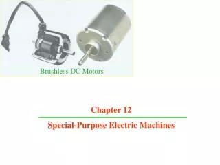
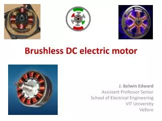
The Stator of a brushless DC motor, as used in a fan. The rotor has been removed Special Electrical Machines, Anuradha Publications
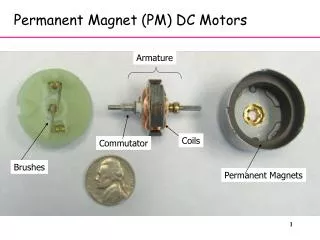
A brushless DC motor is similar to that Brush DC motor in that it has an internal shaft position feedback which tells which windings to switch on at which exact moment. This internal feedback gives both the brush DC motor and the brushless DC motor their unique characteristics: linear speed-torque curves which are well suited for speed and position control and high starting torque. • The internal feedback is accomplished in a brush type DC motor with the mechanical commutator (a series of copper bars which are insulated from each other) and the mechanical brushes through which the current is fed into the commutator bars and switched sequentially into the appropriate winding in the armature. In a BLDC motor, the internal feedback is accomplished by a shaft position feedback sensor of some type which give the required shaft position information to the drive electronics. The drive electronics in turn switches on the appropriate windings at exactly the right moment. This internal shaft position feedback also gives the BLDC characteristics which are similar to the DC the characteristics of a DC motor: linear speed-torque characteristics and high starting torque. The power supplied to a BLDC motor can be DC power but it can also be AC if the drive electronics has the necessary circuitry to convert the AC power to DC. Special Electrical Machines, Anuradha Publications
Before getting into the differences in the various types of motors based on how the rotating field is generated, we now introduce the concept of torque, which is a very important concept in the study of electric motors and common to all types of motors. After all, the purpose of an electric motor (any type of electric motor) is to generate torque (or rotating force). By definition, torque is the multiplication of rotating force and the distance at which the force is being applied. So, intuitively we can see that in order to get greater torque, we need to either increase the force (stronger magnets, more current) and increase the distance at which this force is being applied (physically larger magnets) Special Electrical Machines, Anuradha Publications
Example Brushless DC Motor Operation • This example brushless DC motor has: • An external, electromagnet stator, with magnetic field sensors Special Electrical Machines, Anuradha Publications
Brushless DC Motor Construction A com com A a a c b c b c b com a B C C B com Special Electrical Machines, Anuradha Publications
Brushless DC Motor Operation A com com A a 1 a c b c b c b com a B C C B com Special Electrical Machines, Anuradha Publications
Brushless DC Motor Construction A com com A a a c b c b c b com a B C C B com 2 Special Electrical Machines, Anuradha Publications
Brushless DC Motor Construction A com com A a a c b c b c b com a B C C B com 3 Special Electrical Machines, Anuradha Publications
Brushless DC Motor Construction A com com A a a c b c b c b com a B C C B com 4 Special Electrical Machines, Anuradha Publications
Brushless DC Motor Construction A com com A a a c b c b c b com a B C C B com 5 Special Electrical Machines, Anuradha Publications
Brushless DC Motor Construction A com com A a 6 a c b c b c b com a B C C B com Special Electrical Machines, Anuradha Publications
Brushless DC Motor Construction A com com A a 1 a c b c b c b com a B C C B com Special Electrical Machines, Anuradha Publications
Brushless DC Motor Control Circuit B1 C1 A1 A a c b com B C B2 C2 A2 Special Electrical Machines, Anuradha Publications
Brushless DC Motor Control Circuit B1 C1 A1 A 1 a c b com B C B2 C2 A2 Special Electrical Machines, Anuradha Publications
Brushless DC Motor Control Circuit B1 C1 A1 A a c b com B C B2 C2 A2 2 Special Electrical Machines, Anuradha Publications
Brushless DC Motor Control Circuit B1 C1 A1 A a c b com B C B2 C2 A2 3 Special Electrical Machines, Anuradha Publications
Brushless DC Motor Control Circuit B1 C1 A1 A a c b com B C B2 C2 A2 4 Special Electrical Machines, Anuradha Publications
Brushless DC Motor Control Circuit B1 C1 A1 A a c b com B C B2 C2 A2 5 Special Electrical Machines, Anuradha Publications
Brushless DC Motor Control Circuit B1 C1 A1 A 6 a c b com B C B2 C2 A2 Special Electrical Machines, Anuradha Publications
Brushless DC Motor Control Circuit B1 C1 A1 A 1 a c b com B C B2 C2 A2 Special Electrical Machines, Anuradha Publications
How it Works • Halls Sensors sense the position of the coils • The Decoder Circuit turns appropriate switches on and off • The voltage through the specific coils turns the motor Special Electrical Machines, Anuradha Publications Images courtesy of Servo Magnetics (http://www.servomag.com/flash/2-pole/2pole-bldc-motor.html)
xc Special Electrical Machines, Anuradha Publications
Classification of PMBLDC motors • BLDC with square wave input • 180o pole arc BLDC square wave dc motor • 120o pole arc BLDC square wave dc motor • BLDC with sine wave input Special Electrical Machines, Anuradha Publications
The rotor flux density distribution produced by the permanent magnets is represented by the green space vector Br. A power-processing unit supplies three-phase currents to the stator windings in such a manner that the resultant stator current space vector Is is 90o ahead of the rotor flux vector. The mmfdistribution produced by the stator currents flowing in the stationary three-phase windings is equivalent to that produced by Is flowing in a singlesinusoidally-distributed rotating winding whose magnetic axis lines up with Is as illustrated in this animation. Special Electrical Machines, Anuradha Publications
HALL EFFECT SENSOR • A Hall effect sensor is a transducer that varies its output voltage in response to changes in magnetic field. Hall sensors are used for proximity switching, positioning, speed detection, and current sensing applications. Special Electrical Machines, Anuradha Publications
The Hall effect is a consequence of the Lorentz force in semiconductor materials. When a voltage is applied from one end of a slab of semiconductor material to the other, charge carriers begin to flow. • If at the same time a magnetic field is applied perpendicular to the slab, the current carriers are deflected to the side by the Lorentz force. Charge builds up along the side until the resulting electrical field produces a force on the charged particle sufficient to counteract the Lorentz force. This voltage across the slab perpendicular to the applied voltage is called the Hall voltage. • The Hall effect is illustrated by a semiconductor slab showing magnetic field, applied voltage, forces on electrons and holes, and paths of electrons and holes. Special Electrical Machines, Anuradha Publications
Hall sensor principle In drawing "A", the Hall element takes on a negative charge at the top edge (symbolised by the blue color) and positive at the lower edge (red color). In "B" and "C", either the electric current or the magnetic field is reversed, causing the polarization to reverse. Reversing both current and magnetic field (drawing "D") causes the Hall element to again assume a negative charge at the upper edge. Special Electrical Machines, Anuradha Publications
Hall effect sensor used for commutation • The commutation function may be performed by various shaft position sensors: optical encoder, magnetic encoder (resolver, synchro, etc), or Hall effect magnetic sensors. Small inexpensive motors use Hall effect sensors. • A Hall effect sensor is a semiconductor device where the electron flow is affected by a magnetic field perpendicular to the direction of current flow. It looks like a four terminal variable resistor network. The voltages at the two outputs are complementary. Application of a magnetic field to the sensor causes a small voltage change at the output. The Hall output may drive a comparator to provide for more stable drive to the power device. Or, it may drive a compound transistor stage if properly biased. More modern Hall effect sensors may contain an integrated amplifier, and digital circuitry. This 3-lead device may directly drive the power transistor feeding a phase winding. The sensor must be mounted close to the permanent magnet rotor to sense its position. Special Electrical Machines, Anuradha Publications
3-phase Hall sensor commutated BLDC 2-phase Hall sensor commutated BLDC Special Electrical Machines, Anuradha Publications
Optical Rotor Position Sensor Special Electrical Machines, Anuradha Publications