Download

1 / 25
250 likes | 256 Views
Overview of polarized electron and positron sources. Louis Rinolfi. 16 th April 2016. X-POL workshop Rome. Contents. General concepts to produce polarized e - and e + beams Overview of polarized electron and positron sources

E N D
Overview of polarized electron and positron sources Louis Rinolfi 16th April 2016 X-POL workshop Rome
Contents • General concepts to produce polarized e- and e+ beams • Overview of polarized electron and positron sources • Polarized sources challenges for future high energy colliders • Summary The unpolarizedelectron and positron sources, with all related challenges are not discussed here.
Method to produce polarized e- Laser Photocathode GaAS with superlattice e- beam E = 5 - 10 MeV Electric field DC or RF Cesiated GaAs is the only material for polarized electrons with GaAs/GaAsPsuperlattice crystal => 95 % polarization possible
Some key parameters for polarized e- source • Photocathode • High quantum efficiency • Long life time • Drive laser • Reliable • Synchronization with the machine • Sufficient power • Wavelength tunable • Vacuum • Good dynamic vacuum (with beam on) • Electric field • Avoid break down and field emission
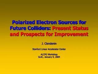
SLC photogun for polarized e- J. Clendenin / SLAC
MAMI photogun for polarized e- K. Aulenbacher / Mainz IPAC 2014 Dresden
ELBE photogun for polarized e- J. Teichert / HZDR Superconducting RF gun at Rossendorf
Building 350 kV DC gun at JLAB 500 kV DC gun in Japan Collaboration KEK / JAEA / Nagoya • Stable operation at 500kV has been confirmed. • 10mA beam generation has been demonstrated. • The gun in cERL commissioning shows good performances.
New Strain-Compensated Super-Lattice N. Yamamoto / Nagoya U. POSIPOL 2014 500 kV DC gun @ KEK => 6.9 MV/m Achieved results: Max Pol. 92 % Max QE 2.2 %
Source parameter comparison Polarized e- beams M. Poelker / JLAB
High current beam at Cornell G. Hoffstaetter / FCC week 2016 - Rome • Peak current of 75mA (world record) • NaKSb photocathode • High rep-rate laser • DC-Voltage source • Source achievements: • 2.6 day 1/e lifetime at 65mA • 8h at 65mA • With only 5W laser power (20W are available) • now pushing to 100mA Simulations accurately reproduce photocathode performance with no free parameters, and suggest strategies for further improvement. Source current can meet ERL needs
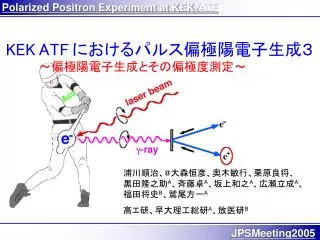
Methods to produce polarized e+ Creation of pair production by circularly polarized photons with • Radiation from helical undulator • Compton backscattering of circularly polarized laser photons by relativistic electrons • Synchrotron radiation from a dipole magnet • Bremsstrahlung from longitudinally polarized electrons (PEPPo collaboration at JLAB) We will mention mainly the two first methods
For future high energy colliders 1) Helical undulator e- e- beam e+ • rays E = 10 -20 MeV E > 100 GeV L > 100 m 2) Compton backscattering with laser Laser e-@10 Mev => g@ 10 keV e-@ 1 Gev=> g@ 10 MeV e- beam e- E = 1 - 6 GeV • rays E = 10 -60 MeV e+
Some key parameters for a polarized e+ source independent of g rays production (where many challenges exist not discussed here) • Photons impinging on the target • Energy • Collimation • Target • Appropriate Z material • Thermal stress • Shock stress • Matching device • Adiabatic • Radiation issues • Shielding
Two large colliders ran with polarized e+ Future lepton colliders (ILC, CLIC, LHeC, CepC, FCC-ee, ….) require polarized e+ beams
ILC Positron Source (TDR) Positron source is located at end of main linacand uses e- beam • Superconducting helical undulator • K=0.92, l=1.15cm, (B=0.86T on the axis), aperture 5.85mm • Max 231m active length • e+ Production Target • 400m downstream the undulator • 0.4 X0Ti alloy • Positron Capture: Pulsed flux concentrator + capture RF • Alternative: quarter wave transformer + capture RF • e+ polarization • By default: ~30% • Polarization upgrade possible up to ~ 60% with a photon collimator
ILC Polarization upgrade W. Gai / ANL 231m RDR undulator, 150GeV drive beam, ¼ wave transformer • With QWT, with a photon collimator to upgrade the polarization to 60%, the positron yield will drop to ~0.8
ILC positron polarization S. Riemann / DESY Demonstration with E-166 experiment at SLAC R. Pitthan & J. Sheppard / SLAC Polarization of 80% was measured for e+ (and e-) in the range 4 – 8 MeV
CLIC Positron Source Compton configuration for polarized e+ 2.424 GeV e+ DR 2.424 GeV 20 turns makes 312 bunches with 4.4x10⁹ e+/bunch e+ PDR and Accumulator ring C = 47 m, 156 ns/turn, 312 bunches with 6.2x10¹⁰ e-/bunch Injector Linac 2.2 GeV 2 GHz RF gun Drive Linac 1.06 GeV 2 GHz Compton ring 2 GHz 50 Hz Pre-injector Linac for e+ 200 MeV g g (10-20 MeV)2.1x10⁹ /turn/bunch e+ 2.6x10⁸ pol. /turn/bunch Stacking cavity e+ target 1 YAG Laser pulse 600 mJ
CLIC positron source data CERN-ATS-2009-086 CLIC Note 788
LHeC Positron Source (CDR) Three rings transformer for polarized e+option extraction ring (N turns) fast cooling ring (N turns) accumulator ring (N turns) E. Bulyak et al.“Performanceof Compton Sources of Polarised Positrons” Positron for LHeC - Brainstorming workshop - May 2011
Leptons flux comparison for future colliders x 7000 x 20 x 300 x 65
FCC-ee parameters Y.Papaphilippou - FCC week 2016
Flux for FCC-ee x 25 Max requested flux is between CLIC and ILC => would be OK
Summary Polarized electron sources for future high energy colliders: 1) The proposed electron source will depend on the accelerator requirements. 2) Polarized electron source implies photoemission. The choice is between DC versus RF. 3) Today the electron source technology is mature, nevertheless many stimulating problems still need be solved. 4) For FCC-ee, the requested flux and polarization level would be reachable. Polarized positron sources for future high energy colliders: Today the requested flux and polarization present several challenges with the present technology but it would be doable. For FCC-ee, test facilities and experimental measurements are strongly recommended to check the performance of polarized electron and positron sources.