Download
1 / 108
1.11k likes | 1.16k Views
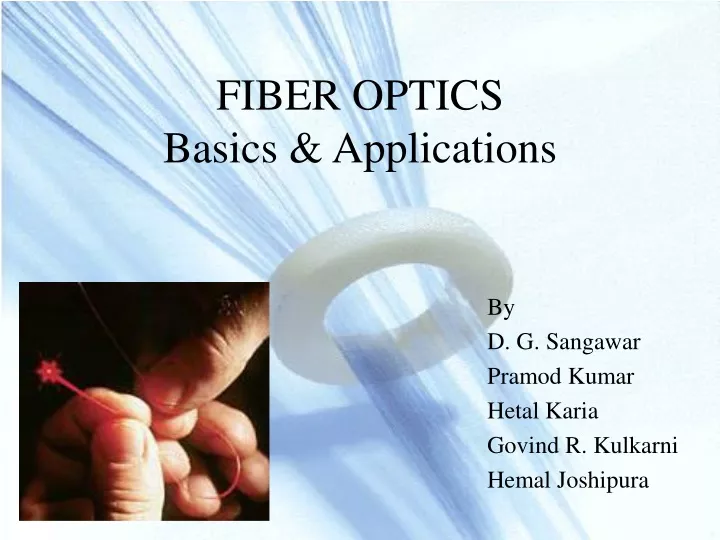
FIBER OPTICS Basics & Applications. By D. G. Sangawar Pramod Kumar Hetal Karia Govind R. Kulkarni Hemal Joshipura. Major Instrument system Networks. References. Understanding Fiber Optics – Jeff Hecht Fiber U Technical Data Sheets

E N D
FIBER OPTICSBasics & Applications By D. G. Sangawar Pramod Kumar Hetal Karia Govind R. Kulkarni Hemal Joshipura
References • Understanding Fiber Optics – Jeff Hecht • Fiber U Technical Data Sheets • Terms & Definitions For Fiber Optic Communications – Methode Electronics • World Wide Web
What Are Fiber Optic Cables ? • Fiber optics (optical fibers) are long, thin strands of very pure glass about the diameter of a human hair. • They are arranged in bundles called optical cables and used to transmit light signals over long distances.
Construction Of Optical Fiber • Buffer Coating : A protective layer such as an Acrylic Polymer applied over the fiber cladding for protective purpose. • Cable Jacket : The outer most protective covering applied over the internal cable elements (i.e. core, cladding, buffer and strength member) • Cladding : The layer of the glass or other transparent material surrounding the light carrying core of an optical fiber. It has lower refractive index than the core.
Advantages of Fiber Optic Cables • Low power • Digital signals • High signal carrying capacity / Bandwidth • Minimum signal degradation • Longer transmission lengths • Immune to RFI, electrical HT cables • Immune to lightening • High Security
Advantages of Fiber Optic Cables • Non-flammable • Thin • Lightweight • Flexible • Less expensive
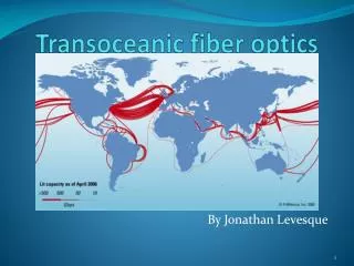
Transmission limitations ? Reliance Infocomm has installed the repeaters every 47 Miles i.e. 75 Km
Terms & Definitions OPTICS • Light : It is an electromagnetic radiation visible to the human eye at 400 to 700 nm. • Refractive Index (h) : It is the ratio of the speed of light in a vacuum to the speed of light in a material i.e. h = Cvac/Cmat • Critical Angle : The angle at which light undergoes Total Internal Reflection.
Terms & Definitions Hardware • Core : The center part of the optical fiber that carries the light. • Cladding : The layer of the glass or other transparent material surrounding the light carrying core of an optical fiber. It has lower refractive index than the core. • Fiber Bundle : A rigid or flexible group of fibers assembled in a unit.
Terms & Definitions Hardware • Connector : A device mounted on the end of the fiber optic cable, light source, receiver, or housing that mates to a similar device to couple into and out of the optical fiber. • Coupler : A device that connects three or more fiber ends, dividing one input between two or more outputs or combining two or more inputs into one output • Pigtail: A short optical fiber permanently attached to a source, detector, convertor or other fiber optic device at one end and an optical connector at the other.
Terms & Definitions Technical • Decibel (dB) : A logarithmic comparison of power levels, defined as ten times the base-ten logarithm of the ration of two power levels. [10log(P1/P2)]. • Attenuation : Diminution of average optical power. Generally expressed in dB without negative sign. • Backscattering : Scattering of light in the direction opposite to that in which it was originally traveling.
Terms & Definitions Technical • Loss : Attenuation of optical signal, normally measured in decibels (dB). • Loss Budget : An accounting of overall attenuation in a system. • Numerical Aperture (NA) : The “light gathering” ability of a fiber defining the maximum angle to the fiber axis at which light will be accepted and propagated through the fiber.
Terms & Definitions Technical • Bandwidth : The highest frequency that can be transmitted in analog operation. Especially for digital system it is information carrying capacity of a system. • FDDI : Fiber Distributed Data Interface is a standard for 100 Mbits/sec fiber optic local area network.
Terms & Definitions Technical • Step-index Fiber: Fiber that has a uniform index of refraction throughout the core that is a step below the index of refraction in the cladding. • Graded-index Fiber: Fiber in which refractive index decreases from center to cladding.
Bending Radius • Bending Radius: Radius of the curvature of fiber that can bend without breaking. • The rule of thumb for minimum bend radius is 1 1/2" for bare, single-mode fiber; 10 times the cable's outside diameter (O.D.) for non-armored cable; and 15 times the cable's O.D. for armored cable.
Types Of Optical Fiber • Single Mode • Used to transmit signals in single mode per fiber
Types Of Optical Fiber • Single Mode • Core Diameter : 8 to 10 mm • Cladding Diameter : 125 mm
Types Of Optical Fiber • Multi Mode - Used to transmit signals in multiple modes per fiber. • Step Index – Mainly used for short data links at low speed.
Types Of Optical Fiber • Multi Mode Step Index • Core Diameter : 100 mm • Cladding Diameter : 140 mm
Types Of Optical Fiber • Graded Index – have broader bandwidth than Step Index multi mode fiber. • Smaller cores than Step Index multi mode fiber.
Types Of Optical Fiber • Multi Mode Graded Index • Core Diameter : 50 / 62.5 mm • Cladding Diameter : 125 mm
Fiber optic Performance Indices • Attenuation • Acceptance angle • Numerical aperture (NA) • Light source type
Fiber optic Performance Factors • Atteuation: Decrease in power of data carrying signal. • 3 dB loss equals 50% loss of signal • Negatively affects transmission speeds and distances of all cabling systems.
Fiber optic Performance Indices • Causes of attenuation • Excessive gap between fibers in a connections • Improperly installed connectors • Impurities in fiber itself • Excessive bending of the cable • Excessive stretching of the cable
Fiber optic Performance Indices • Acceptance angle :over which MM fiber can accept light as an input to that fiber. • The greater the acceptance angle diff between two or more signals in a MM fiber , greater the effect of modal dispersion.
Fiber optic Performance Indices • Numerical Aperture: Number that reflects the ability of the particular optical fiber to accept light. • The value of NA is between 0 and 1. • A value 0 indicates that the fiber gathers no light • A value 1 indicates that the fiber will accept all light it’s exposed to.
Fiber optic Performance Indices • Difference between high and low NA value
Fiber optic Performance Indices • Lower the NA ,less light that gets accepted into the fiber, thus the less distance the signal can travel, but more possible bandwidth available. • Higher the NA ,means that the signal can travel farther, but there is lower bandwidth for that signal.
Fiber optic Performance Indices Light Sources : LED (Light Emitting Diode) – • Emits light at 830 to 850 nm.
Fiber optic Performance Indices ELED (Edge Light Emitting Diode) – • Emits light at 1300 nm. • Emits the light from the edges only, hence receiver receives more intense beam of light as compare to LED.
Fiber optic Performance Indices LASER (Light Amplification by Stimulated Emission of Radiation) – • Emits light at 1300 to 1500 nm. • Most powerful as compared to LED and ELED.
Test Equipments Test Standards Group • Test procedure for monitoring performance of fiber optic cables have been standardized by international standards bodies like : ITU International Telecommunication Union IEC International Electro technical Commission EIA Electronic Industries Association
Test Equipments • Visible Light Source [Flashlight / LED] • Laser Source [HeNe (633 nm)] • Optical Power Meter • Optical Talk Set • Fiber Identifier • Cold Clamp System
Test Equipments Visible Light Source • OTDR (Optical Time Domain Reflectometer)
Test Equipments Optical Power Meter • Uses semiconductor detectors (Si, Ge, InGaAs). • To interface to variety of connectors a removable connector adaptor is provided. • Reads power in mW, dBm and some relative dB.
Test Equipments Optical Power Meter • Calibrated at 660, 780, 850, 1310 & 1550 nm. • Covers wide measurement range (0 to –60dBm) • All materials have uncertainty of ± 5%. • For CATV testing meters with range of +20 to –50dBm are used.
Test Equipments Light Source • Used in conjunction with Power meter to measure optical loss in fibers and connectors. • Can be LEDs (-20dBm) or LASERS (0 to –10dBm) • For SM or MM. • Wavelength : 660, 850, 1310, 1550 nm.
Test Equipments Fiber Optic Talk Sets • Used during FO installations for communicating on installed cable.
Test Equipments Fiber Identifiers • Bends fiber & light coupled out is detected by a detector. • Used to find live fibers. • Used with light source to find specific fiber from large multi fiber cable. • Used on buffered and jacketed single fiber.
Cold Clamp System • Exact location of fault can be determined by using with OTDR. • Liquid Nitrogen has to be filled in after installing at the suspected place detected by OTDR. • Nitrogen creates temporary optical loss of 0.2 to 1 dB, which can be picked by OTDR with its distance relative to the fault.