Download
1 / 20
200 likes | 318 Views
Sticking of CH 3 radicals and H, He, Ne, Ar- bombardment simulations on fusion first wall structures. Petra Träskelin , Kai Nordlund, Emppu Salonen Accelerator Laboratory. Outline. Introduction Hydrogen and hydrocarbon reactions on fusion first wall s. Simulations

E N D
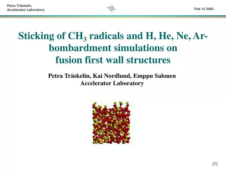
Sticking of CH3radicals and H, He, Ne, Ar- bombardment simulations on fusion first wall structures Petra Träskelin, Kai Nordlund, Emppu SalonenAccelerator Laboratory
Outline • Introduction • Hydrogen and hydrocarbon reactions on fusion first walls • Simulations • Chemical sputtering by H impinging onto a-C:H • CH3 radical sticking onto dangling bonds on C(111) • H, He, Ne, and Ar cumulative bombardment on a-C:H • Conclusions and outlook • Implications for fusion modelling
Fusion first wall and divertor - problems • plasma particles leak outside the closed magnetic field lines and interact with the chamber walls • critical problem - choice of the plasma-facing components • most severe damage to the first wall is caused by the intense (1022 – 1024 ions/m2s) bombardment by hydrogenic particles • erosion of plasma facing components, degradation of their thermal and mechanical properties and deposition of the radioactive tritium in the wall structures • fusion plasma purity compromised as eroded impurity species from the plasma facing components enter the plasma and dilute it. • radiation losses, proportional to the atomic number Z of the impurity species, which further lead to cooling of the plasma and the extinction of the fusion reaction.
Why carbon ? • High thermal conductivities • Excellent thermal shock resistance • Does not melt (sublimation point of graphite is 3640 K) • Low activation material • Possible to tolerate much higher C impurity concentrations in the core plasma, than in the case of high-Z materials like Mo and W • Typically different types of graphite or carbon fiber composites are used in present day tokamaks
Carbon problems... • Oxygen etches carbon efficiently with the formation of volatile molecules (CO, CO2 ...) • Continuing high-flux bombardment by hydrogen ions and neutrals eventually results in • A distorted a-C:H structure at the surface of the divertor plates. [J. Küppers, Surf. Sci. Rep. 22, 249 (1995)] • Estimates of the erosion rates indicate too short operational times for carbon plasma facing components in actual reactors. [G. Janeschitz and ITER JCT and HTs, J. Nucl. Mater. 290-293, 1 (2001)] • Redeposited hydrocarbon species not only on the divertor plates but also in other parts of the vacuum chamber, forming C:H films. [P. Andrew et al., J. Nucl. Mater. 266-269, 153 (1999)] • Accumulation of tritium in the vessel walls.
Carbon erosion by hydrogen • Physical sputtering well understood, results in significant erosion of at hydrogen impact energies above ~50 eV[J. Roth and Carcía-Rosales, Nuclear Fusion 36 (1996) 1647] • Physical sputtering also by He ash ion bombardment, but sputtering yields at divertor-relevant energies are lower than those due to the hydrogenic species[W. Eckstein, J. Nucl. Mater. 248 (1997) 1] • At lower hyperthermal energies, where no physical sputtering is expected, C erosion yields comparable to those due to physical sputtering are observed • Relevant to detached divertor plasmas with ion impact energies below ~25 eV • Computational tools and atomic force models offers alternative way of studying carbon erosion mechanisms
CH3radical simulations • CH3 and C2H2 are most abundantly sputtered species from plasma-facing carbon materials in fusion devices[E Vietzke and A. A. Haasz, in Physical Processes of the Interaction of Fusion Plasmas with Solids, Chap. 4 (1996), E. Salonen et al. Contrib. Plasma Phys. 42 (2002) 458] • Models based on measurements indicates these species two most important growth species in a filament-assisted diamond growth [D. G. Goodwin and G. G. Gavillet, J. Appl. Phys. 68 (1990) 6393] • Additional flux of atomic hydrogen interacting simultaneously with CH3 radicals on the surface enhances the sticking cross section by two orders of magnitude[A. von Keudell, This Solid Films 402 (2002) 1] • CH3 is important for C:H film growth: • high concentration in the feed gas • adsorption on unsaturated carbon sites • creation of new unsaturated carbon sites
CH3 radical simulations • Quantum-mechanical force model, tight-binding • [D. Porezag et al. Phys. Rev. B 51 (1995) 12947, M. Elstner et al. Phys. Rev. B 58 (1998) 7260] • Describes well the chemistry in C-H systems giving a rigorous quantum mechanical representation • Calculates the energy by solving the Schrödinger equation for electrons in the field of atom cores • Based on a second order expansion of the Kohn-Sham total energy in density functional theory with respect to charge fluctuations • Empirical force model based on the Brenner hydrocarbon potential • Obtained from an analytical function of atom coordinates usually fitted to experimental data • Computationally less intensive while still describing bond formation and breaking correctly • Allows to achieve more comprehensive statistics in MD simulations
CH3 radical simulations 7 DB: sticking cross section = average area per surface site
CH3 radical simulations angles of incidence • Sticking probability vs. distance from unsaturated carbon site at different angles of incidence of CH3 • Dependence of sticking cross section on angle of incidence of incoming CH3 radical
CH3 radical simulations • Geometrical model, describing the angle dependence • C, H covalent radius 0.77, 0.35 Å
CH3 radical simulations, conclusions • Sticking cross section highly dependent on • Surface configuration • Angle of incidence of incoming CH3 radical • Angle dependence described with a geometrical model • Steering effect observed • Unusual bonding configurations • Implications for fusion device modeling • Our results indicate different sticking cross sections needed for the description of different kinds of hydrocarbon films
H, He, Ne, Ar cumulative bombardment simulations • Annealing of the cell • Periodic boundary conditions in x-, y- and z- directions • Equilibration at ~4000 K • Quenching 5-10 ps • Repeating procedure • Putting cells under high pressures in order to achieve desired sp²/sp³ fractions for the carbon atoms • Relaxing of samples at zero pressure and temperature • Removing periodic boundary condition in z-direction • Fixation of atoms at 2 Å at bottom • Equilibration at 300 K, 50 ps • 1000 atoms, 15 x 15 x 30 Å • H/C ratio ~0.4 (exp. observed saturation value at 300 K)[J. Roth et al., J. Nucl. Mater. 93-94 (1980) 601] • Minimum separation C-C 1.5 Å, H-C 1.1 Å.
H, He, Ne, Ar cumulative bombardment simulations • Final density ~2.4 g/cm3 • Three and four fold carbon fraction 60-70 % and 25-40 % • H, He, Ne, or Ar atom placed above the surface, distance larger than the cutoff radius of the model • Speed equivalent to 1-5 or 10 eV and aimed at surface • Cell randomly shifted along x and y directions between every new simulation run • 8000-10000 simulations (bombardment+relaxation)
High-flux hydrogen irradiation • Ion energies according to Maxwellian distributions with root-mean-square energies of 1 and 10 eV • Evolution of number of H for a-C:H surfaces impinged on by H ions [E. Salonen et al, Phys. Rev. B 63 (2001) 195415]
Swift chemical sputtering • Process of bond breaking and erosion which takes place during the first 500 fs of the impact simulation • Breaking of covalent C-C bonds by energetic particles • ion penetrates between two C atoms, forces them apart, and bonds to C atom leaving the surface [E. Salonen et al, Europhys. Lett. 52 (2000) 504-510, E. Salonen et al, Phys. Rev. B, 63 (2001) 195415]
H, He, Ne, Arcumulative bombardment simulations • Noble gas/hydrogen ratio 1/10 • 5 and 10 eV • C2Hx species dominates. • Erosion yields from 5 eV simulations much lower than from 10 eV. • NO erosion of larger (CxHy x > 4) species in the first 500 cumulative bombardment events
H, He, Ne, Ar cumulative bombardment simulations • Evolution of the number of carbon and hydrogen atoms • NO differences in the erosion yields between the simulations with different noble gases • Ions having larger energies also lead to enhanced erosion
H, He, Ne, Ar cumulative bombardment simulations • Simulations performed using Maxwell energy distribution instead of mono-energetic irradiation • Hydrogen, 2, 3, 4, and 5 eV
H, He, Ne, Ar cumulative bombardment simulations, conclusions • Within statistical uncertainties there are NO differences in erosion yields between simulations with different noble gases, at least for a noble gas hydrogen ratio of 1/10 • Ions having larger energies also lead to enhanced erosion • No erosion of larger (CxHy x > 4) species in the first 500 cumulative bombardment events • Eroded species mainly C2Hy (y=1, 2, 3, 4, 5, 6)