Download
1 / 12
130 likes | 298 Views
OVERFILL PREVENTION DEVICE. Mechanism. A. Where to place it ?. The OPD is compatible with all tanks equipped with manhole plates. 1. 1. The OPD has to be set on the filling pipe inside the tank. 2. 1. Manhole plate. 1. 1. 2. B. Technical characteristics. 3. 4. THE FLOAT. 1.

E N D
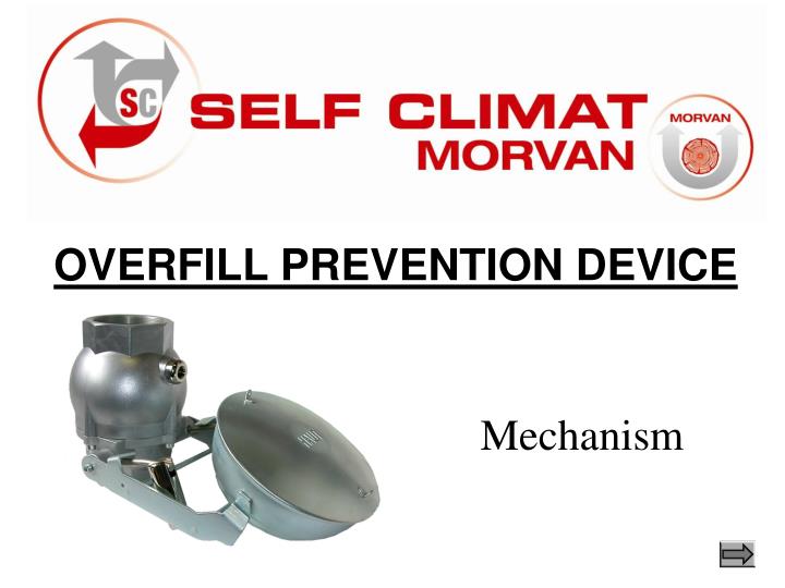
OVERFILL PREVENTION DEVICE Mechanism
A. Where to place it ? The OPD is compatible with all tanks equipped with manhole plates . 1 1 The OPD has to be set on the filling pipe inside the tank. 2 1 Manhole plate 1 1 2
B. Technical characteristics 3 4 THE FLOAT 1 THE BALANCE WEIGHT 2 1 THE VALVE 3 2 THE BALANCE SHAFT 4 THE PISTON 5 6 5 THE CHAMBER 6 Red area = crossing liquid area
C. Mechanism • The 4 steps of the OPD mechanism: • THE FILLING STAGE • THE CLOSURE (level N1) • THE EMPTYING OF THE FLEXIBLE AND THE PIPE • 4) THE CLOSURE (level Nmax) Manhole plates Valve Nmax level Balance Weight N1 level Float Low position Balance shaft n°1 Balance shaft n°2
C. Mechanism 1) THE FILLING STAGE The float is in low position and the piston in the high position. The liquid flows through the OPD body (red area). The float gradually rises according to the tank filling level.
C. Mechanism 2) THE CLOSURE (level N1) The balance Weights are carried along by the rise of the balance shaft on the float. The piston partially obstructs the flow which enables the increase of the hydraulic pressure in the chamber.
C. Mechanism 2) THE CLOSURE (level N1) The hydraulic pressure let the Balance weights breaking away from the balance shaft. They finish their rise independently to the float while the piston sits on its seat. The N1 level is reached and ensures a full closure.
C. Mechanism 3) THE EMPTYING OF THE FLEXIBLE AND THE PIPE The different steps of the emptying. • Closing the tanker truck valve. • Elimination of the hydraulic pressure in the chamber thanks to the flight hole pierced on the wrapping of the piston chamber and thanks to the opening valve. • Reopening of the piston • Emptying of the flexible (minimum 150 litters)
C. Mechanism 4) LEVEL Nmax In the event of accidental decanting, repeated emptying operations or failure to comply with the flows stipulated by current standards, the overfill prevention device can reach a maximum level Nmax which prevents any further filling until the liquid level has fallen in the tank.
E. Conformity All our OPD are certified ATEX (protection II Gc IIB T6), are complied with the 94/9/CE directive and with the European norm EN 13616.
I am at your disposal for any further information. Charles BROCHET +33 (0)1 60 05 18 58 Export@selfclimat.com