Download
1 / 5

E N D
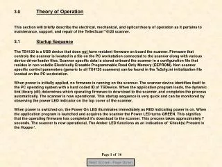
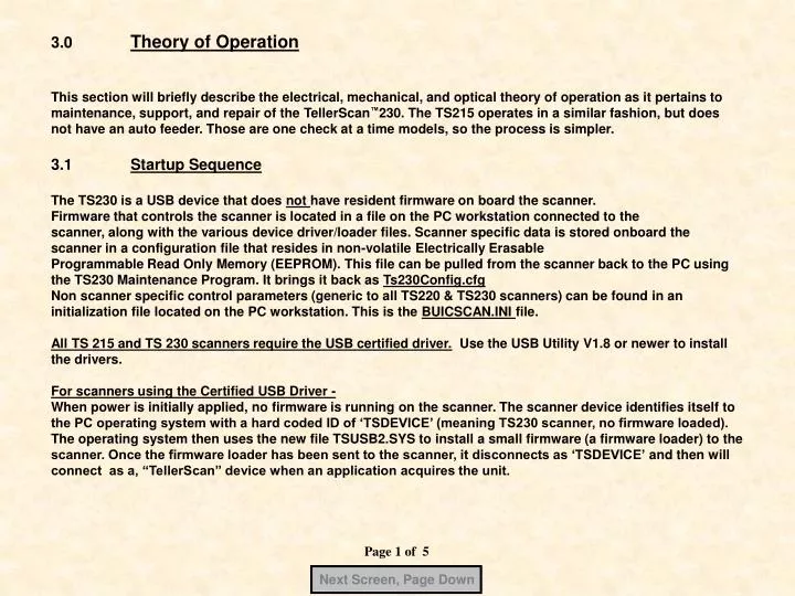
Next Screen, Page Down 3.0 Theory of Operation This section will briefly describe the electrical, mechanical, and optical theory of operation as it pertains to maintenance, support, and repair of the TellerScan™230. The TS215 operates in a similar fashion, but does not have an auto feeder. Those are one check at a time models, so the process is simpler. 3.1 Startup Sequence The TS230 is a USB device that does not have resident firmware on board the scanner. Firmware that controls the scanner is located in a file on the PC workstation connected to the scanner, along with the various device driver/loader files. Scanner specific data is stored onboard the scanner in a configuration file that resides in non-volatile Electrically Erasable Programmable Read Only Memory (EEPROM). This file can be pulled from the scanner back to the PC using the TS230 Maintenance Program. It brings it back as Ts230Config.cfg Non scanner specific control parameters (generic to all TS220 & TS230 scanners) can be found in an initialization file located on the PC workstation. This is the BUICSCAN.INI file. All TS 215 and TS 230 scanners require the USB certified driver. Use the USB Utility V1.8 or newer to install the drivers. For scanners using the Certified USB Driver - When power is initially applied, no firmware is running on the scanner. The scanner device identifies itself to the PC operating system with a hard coded ID of ‘TSDEVICE’ (meaning TS230 scanner, no firmware loaded). The operating system then uses the new file TSUSB2.SYS to install a small firmware (a firmware loader) to the scanner. Once the firmware loader has been sent to the scanner, it disconnects as ‘TSDEVICE’and then will connect as a, “TellerScan” device when an application acquires the unit. Page 1 of 5
Next Screen, Page Down 3.1 (Continued) When the application program loads, the dynamic link library (dll) determines which operating firmware to download to the scanner, and completes the process automatically. The scanner is now operational. This startup sequence is very quick and can be monitored by observing the LED indicators on the top cover of the scanner. When power is switched on, the right LED illuminates RED. This immediately indicates power is on. When an application acquires the scanner, the LED turns green. If the LED doesn’t illuminate green at this time, there is a disconnect between the PC and the scanner. Check that the certified USB2 cable is properly installed and the PC USB2 port is operational and enabled. It can also mean that the PC could not find the firmware. Check the Device Manager under USB devices to see if ‘TSdevice’ is there. An ‘Unknown Device’ indicates Windows did not properly install the device. When the application program is launched, the full operating firmware is downloaded to the Scanner. This process takes approximately 3 seconds with USB2.0 (over 30 seconds with USB 1.1). The scanner is now operational and the left LED functions as an indication of ‘Check(s) Present in the Hopper’. The TS230 uses a dual purpose sensor. The Sync sensor, which senses the leading edge of the document. Then after approximately ¼”, it turns into a Double Feed sensor. The TS230 series uses specific exit sensors to sense the documents passing through the scanhead area and into the exit pocket. On TS230 models, the entry solenoid engages when the scan cycle starts and then the entry solenoid is pulsed by a microprocessor on the main mother board which holds the solenoid in until the entry pocket is empty. Review sections 3.2 through 3.11 in the TS230 Service Manual PDF, included on this CD, for additional information about the operation of the specific sensors, MICR, Endorsement and Scanheads. Page 2 of 5
Next Screen, Page Down TS220E –Model 146 Overhead View (for comparison) Twin Motor Design Stationary Foam Roller LED board with Microprocessor, and no interlock switch Entry Solenoid Auto Feeder – 25 to 40 Items Entry Drive Roller Entry Sensor Sync & double feed sensor Double Feed Adjustment Page 3 of 5
Next Screen, Page Down TS215 – Overhead View Single Hand Drop & Slide Main Drive Rollers Exit Sensor LED board with no interlock switch Entry Slot Sync sensor Entry Sensor Entry Drive Roller Page 4 of 5
Next Screen, Page Down TS230 – Overhead View Model 35/ 65 / 100 Main Driver Rollers Exit Sensor Stationary Foam Roller LED board with no interlock switch Entry Solenoid Auto Feeder – 1 to 50 Items Ink Jet Platform (Optional) Entry Sensor Entry Drive Rollers Sync & double feed sensor Double Feed Adjustment Page 5 of 5