Download
1 / 30
300 likes | 306 Views
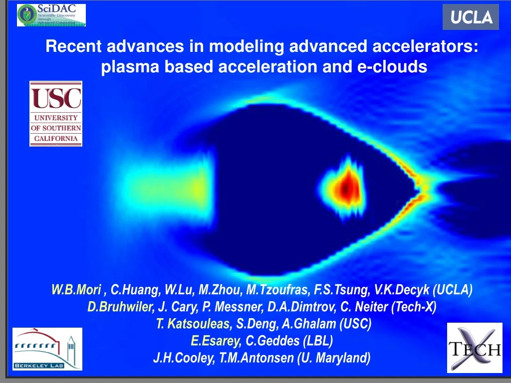
Recent advances in modeling advanced accelerators: plasma based acceleration and e-clouds W.B.Mori , C.Huang, W.Lu, M.Zhou, M.Tzoufras, F.S.Tsung, V.K.Decyk (UCLA) D.Bruhwiler , J. Cary, P. Messner, D.A.Dimtrov, C. Neiter (Tech-X) T. Katsouleas , S.Deng, A.Ghalam (USC)

E N D
Recent advances in modeling advanced accelerators: plasma based acceleration and e-clouds W.B.Mori , C.Huang, W.Lu, M.Zhou, M.Tzoufras, F.S.Tsung, V.K.Decyk (UCLA) D.Bruhwiler, J. Cary, P. Messner, D.A.Dimtrov, C. Neiter (Tech-X) T. Katsouleas, S.Deng, A.Ghalam (USC) E.Esarey, C.Geddes (LBL) J.H.Cooley, T.M.Antonsen (U. Maryland)
Particle AcceleratorsWhy Plasmas? Conventional Accelerators Plasma • Limited by peak power and breakdown • 20-100 MeV/m • No breakdown limit • 10-100 GeV/m
Concepts For Plasma Based Accelerators • Plasma Wake Field Accelerator(PWFA) • A high energy electron bunch • Laser Wake Field Accelerator(LWFA, SMLWFA, PBWA) • A single short-pulse of photons • Drive beam • Trailing beam Wake excitation Evolution of driver and wake Loading the wake with particles Physics necessitates the use of particle based methods: Many length and time scales for fields + particles--grand challenge!
Wake excitation is nonlinear: Trajectory crossingRosenzweig et al. 1990 Puhkov and Meyer-te-vehn 2002Ion column provides ideal accelerating and focusing forces Trajectory crossing Beam driver Laser driver
Plasma Accelerator Progress and the “Accelerator Moore’s Law” Slide 2 LOA,RAL LBL ,RALOsaka Courtesy of Tom Katsouleas
Computational cycle (at each step in time) Particle positions push particles weight to grid Lorentz Force t What Is a Fully Explicit Particle-in-cell Code? Not all PIC codes are the same! • Maxwell’s equations for field solver • Lorentz force updates particle’s position and momentum Interpolate to particles Typical simulation parameters: ~108-109 particles ~10-100 Gbytes ~105 time steps ~104-105 cpu hours
Advanced accelerators:Before SciDAC 5000+ node hours for each GeV of energy One 3D PIC code
Accomplishments and highlights:Code development • Four independent high-fidelity particle based codes • OSIRIS:Fully explicit PIC • VORPAL: Fully explicit PIC + ponderomotive guiding center • QuickPIC:quasi-static PIC + ponderomotive guiding center • UPIC:Framework for rapid construction of newcodes--QuickPIC is based on UPIC: FFT based • Each code or Framework is fully parallelized. They each have load balancing and particle sorting.Each production code has ionization packages for more realism. Effort was made to make codes scale to 1000+ processors.
OSIRIS:full parallel PIC for plasma accelerators • Successfully applied to various LWFA and PWFA problems • Mangles et al., Nature 431, 538 (2004). • Tsung et al., Phys. Rev. Lett., 93, 185002 (2004) • Blue et al., Phys. Rev. Lett., 90 214801 (2003) • Code • Moving window • Parellized using domain decompostion • Two charge conserving deposition schemes • Current and field smoothing • Field + Impact Ionization • Static load balance. • Well tested • Modern (object-oriented, Fortran 95 techniques) • Parallel (general domain decomposition) or Serial • Cross-platform (UNIX, Linux, AIX, OS X, MacMPIC) • Based on a well proven Fortran 77 code • Sophisticated 3D data diagnostics • OSIRIS development team • UCLA(F. S. Tsung, J. W. Tonge), USC (S. Deng), IST (R. A. Fonseca and L. O. Silva), Ecolé Polytechnique (J. C. Adam), and RAL (R. G. Evans). • See http://exodus.physics.ucla.edu/
Colliding laser pulses Particle beams 104 s(N) VORPAL scales well to 1,000’s of processors VORPAL – parallel PIC & related algorithms for advanced accelerators • Successfully applied to various LWFA problems • Geddes et al., Nature 431, 538 (2004). • Cary et al., Phys. Plasmas (2005), in press (invited). • Recently implemented algorithms • Ponderomotive guiding center treatment of laser pulses • PML (perfectly matched layer) absorbing BC’s • implicit 2nd-order & explicit 4th-order EM • Many other capabilites/algorithms (only a sample here): • Impact & field ionization; secondary e- emission • Fluid methods for plasmas; hybrid PIC/fluid • Modern (object-oriented, C++ template techniques) • Parallel (general domain decomposition) or Serial • Cross-platform (Linux, AIX, OS X, Windows) • VORPAL development team • J. Cary (Tech-X/CU), C. Nieter, P. Messmer, D. Dimitrov, J. Carlson, D. Bruhwiler, P. Stoltz, R. Busby, W. Wang, N. Xiang (CU), P. Schoessow, R. Trines (RAL) • See http://www.txcorp.com/technologies/VORPAL/ • Highly leveraged via SBIR funds: DOE, AFOSR, OSD
Code development:QuickPIC Code features: • Based on UPIC parallel object-oriented plasma simulation Framework. • Underlying Fortran library is reliable and highly efficient • Multi-platform, Mac OS 9/X, Linux/Unix. • Dynamic load balancing Model features: • Highly efficient quasi-static model for beam drivers • Ponderomotive guiding center + envelope model for laser drivers. • Can be 100+ times faster than conventional PIC with no loss in accuracy. • ADK model for field ionization. Applications: • Simulations for PWFA experiments, E157/162/164/164X/167 • Study of electron cloud effect in LHC. • Plasma afterburner design Scalability: • Currently scales to ~32 processors • With pipelining should scale to 10,000+ processors afterburner hosing E164X
QuickPIC loop: 2-D plasma slab Wake (3-D) Beam (3-D): Laser or particles
2D loop end 2D loop begin 3D loop end 3D loop begin Initialize beam Initialize plasma Field Solver Maxwell equations in Lorentz gauge Call 2D routine Reduced Maxwell equations Push beam particles Push plasma particles Iteration Deposition Deposition Quasi-static Model including a laser driver Laser envelope equation:
Node 2 Node 1 Node 0 Node 3 Communication x 3D domain decomposition z y Node 3 Node 0 Node 1 Node 2 Beam Network Overhead Plasma y x 2D domain decomposition with dynamic load balancing Parallelization for QuickPIC Beam • Scales up to 16-32 CPUs for small problem size. • Network overhead dominates on Dawson cluster (GigE). • 4 times performance boost with infiniband hardware. • With pipelining should scale to 10,000+ processors
Accomplishments and highlights:Physics • Development of new reduced models (QuickPIC) and benchmarking of codes (OSIRIS vs. Vorpal, QuickPIC vs. OSIRIS, Vorpal vs. Vorpal PG) • Code validation (by adding more realism): • Modeling of PWFA experiments at SLAC in 3D: 4GeV energy gain in ~10cm (OSIRIS and QuickPIC). • Identified self-ionization as a plasma source option in PWFA (OOPIC, Vorpal, OSIRIS) • Modeling LWFA experiments at LBNL and RAL: 100MeV monoenergetic beams in ~1mm (OSIRIS and VORPAL). • New physics: • Modeling PWFA Afterburner (energy doubler) stages: From 50 to 100 GeV and from 500 to 1000 GeV (QuickPIC). • Modeling possible 1GeV mono-energetic LWFA stages: with and without external optical guiding (OSIRIS and VORPAL).
e- driver e+ driver e- driver with ionization laser driver QuickPIC Benchmark: Full PIC vs. Quasi-static PIC Benchmark for different drivers • Excellent agreement with full PIC code. • More than 100 times time-savings. • Successfully modeled current experiments. • Explore possible designs for future experiments. • Guide development on theory. 100+ CPU savings with “no” loss in accuracy
Code benchmarking:Vorpalfully explicit vs. ponderomotive guiding center • Removes fast time-scale of laser pulse • orders of magnitude faster than full PIC • can simulate 3 cm LBNL plasma channel in 2D in a few processor-hours • Excellent comparison w/ 2D PIC • good agreement seen for a0~1 • accelerating wake fields (upper fig.) • normalized particle velocities (lower fig.) • particle trapping seen at larger values of a0
Located in the FFTB 25 m Modeling self-ionized PWFA experiment with QuickPIC E164X experiment FFTB QuickPIC simulation
+4 +2 Relative Energy (GeV) 0 -2 -4 -5 0 +5 X (mm) Full-scale simulation with ionization of E-164xx is possible using a new code QuickPIC • Identical parameters to experiment including self-ionization: Agreement is very good!
Recent highlights: LWFA simulations using full PIC • Phys. Rev. Lett. by Tsung et al. (September 2004) where a peak energy of 0.8 GeV and a mono-energetic beam with an central energy of 280 MeV were reported in full scale 3D PIC simulations. • 3 Nature papers (September 2004) where mono-energetic electron beams with energy near 100 MeV were measured. Supporting PIC simulations were presented. • SciDAC members were collaborators on two of these Nature publications and SciDAC codes were used. • Cover is a Vorpal simulation
3D PIC Simulations with no fitting parameters: Nature papers, “agreement” with experiment: What is the metric for agreement? 3D Simulations for: Nature V431, 541 (S.P.D Mangles et al) • In experiments, the # of electrons in the spike is 1.4 108. • In our 3D simulations, we estimate of 0.9 108 electrons in the bunch.
State-of- the- art ultrashort laser pulse 0 = 800 nm, Dt = 30 fs I = 3.4x10¹⁹ W/cm-2, W =19.5 mm 256 cells 80.9 mm 256 cells 80.9 mm 4000 cells 101.9 mm Full scale 3D LWFA simulation using OSIRIS:200TW, 40fs • Simulation Parameters • Laser: • a0 = 4 • W0=24.4 l=19.5 mm • wl/wp = 33 • Particles • 2x1x1 particles/cell • 500 million total • Plasma length • L=.7cm • 300,000 timesteps Laser propagation Plasma Background ne = 1.5x1018 cm-3 Simulation ran for 75,000 hours on 200 G5 x-serve processors on DAWSON (~5 Rayleigh lengths)
Simulations are leading experiments: 200TW 30fs laser----1.5 GeV beam in ~cm • Laser blows out all plasma electrons leading to an ideal accelerating structure • Isolated beams are self-injected. • Beams become mono-energetic as they outrun the wake. OSIRIS simulation
One goal is to build a virtual accelerator:A 100+ GeV-on-100+ GeV e-e+ ColliderBased on Plasma Afterburners 3 km 30 m Afterburners
Advanced accelerator milestone: Full-scale simulation of a 1TeV afterburner is possible using QuickPIC • Before SciDAC: 5,000,000+ node hours at NERSC (was not done) • Because of SciDAC: 5,000 node hours on the DAWSON Cluster (2.3 Ghz x-serves) • We use parameters consistent with the International Linear Collider “design” • We have modeled the beam propagating through ~25 meters of plasma!
Advanced accelerators:After SciDAC • 3D modeling with realism-2 explicit PIC codes plus a parallel Framework • Code benchmarking • Code validation-Full scale 3D modeling of experiments • Efficient and high fidelity reduced description models: Rapid construction of fully parallelized code • Extension of plasma techniques to conventional accelerator issues: e-cloud • Rapid progress has resulted from: • Faster computers • New algorithms • Reuseable software • Scientific discovery: • 3 Nature articles and 8 Phys. Rev. Lett.’s
Vision for the future:High fidelity modeling of .1 to 1TeV plasma accelerator stages • Physics Goals: • A) Modeling 1to 10 GeV plasma accelerator stages: Predicting and designing near term experiments. • B) Extend plasma accelerator stages to 250 GeV to 1TeV range: understand the physics and scaling laws • C) Use plasma codes to definitively model e-cloud physics: • 30 minutes of beam circulation time on LHC • ILC damping ring • Software goals: • A) Add pipelining into QuickPIC: Allow QuickPIC to scale to 1000’s of processors. • B) Add self-trapped particles into QuickPIC and ponderomotive guiding center Vorpal packages. • C) Improve numerical dispersion* in OSIRIS and VORPAL. • D) Scale OSIRIS, VORPAL, QuickPIC to 10,000+ processors. • E) Merge reduced models and full models • F) Add circular and elliptical pipes* into QuickPIC and UPIC for e-cloud. • G) Add mesh refinement into* QuickPIC, OSIRIS, VORPAL,and UPIC. • H) Investigate the utility of fluid and Vlasov models. * Working with APDEC ISIC
beam Initial plasma slab 1 2 3 4 beam Initial plasma slab 1 2 3 4 solve plasma response solve plasma response solve plasma response solve plasma response solve plasma response update beam update beam update beam update beam update beam Without pipelining: Beam is not advanced until entire plasma response is determined With pipelining: Each section is updated when its input is ready, the plasma slab flows in the pipeline. Pipelining: scaling quasi-static PIC to 10,000+ processors
Advanced accelerators:Goals • Develop reusable software based on particle-in-cell methods that scales to 1000+ processors. • Develop codes that use this reusable software and which include the necessary physics modules. • Develop reduced description codes to reduce cpu and memory needs. • Benchmark codes against each other and validate codes against experiments. • Use validated codes to discover ways to scale plasma based accelerator methods to .1 to 1 TeV.