Download
1 / 31
310 likes | 315 Views
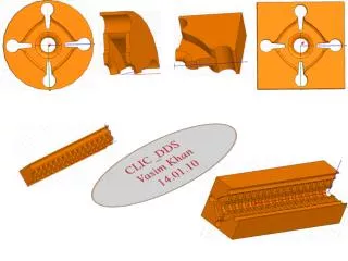
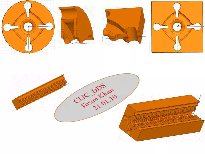
CLIC_DDS Vasim Khan 21.01.10. DDS1 : Plain curve ; DDS2 : Curve with dots. DDS1 : Plain curve ; DDS2 : Curve with dots. DDS1 : Plain curve ; DDS2 : Curve with dots. Major changes DDS1 to DDS2. DDS1. DDS2. DDS1. DDS2. Problems in improving gamma. Rc = 6.2mm. Rc = 7.2mm.

E N D
CLIC_DDS Vasim Khan 21.01.10
DDS1 : Plain curve ; DDS2 : Curve with dots Major changes DDS1 to DDS2 DDS1 DDS2
DDS1 DDS2
Problems in improving gamma Rc = 6.2mm Rc = 7.2mm
Matching cells : First end cell Beam pipe Beam pipe 10.95 mm b a Last matching cell with dimensions of Cell 1 First matching cell with dimensions of Cell 1 Cell 1
S11 ∆a= 0 mm ∆b= 0 mm ∆ = Change in dimensions w.r.t. Cell # 1 Eigen mode solutions 6 vertical dashed lines: 3 E-E B.C. +3 H-H B.C. S21
Optimisation : In progress S21 = 0.984 F = 11.996 GHz S11 = 0.122 ∆a = +0.221 mm ∆b= 0 mm ∆ = Change in dimensions w.r.t. Cell # 1
Crab cavity profile : 28.08.09 TM01 Fundamental mode 8.0 GHz TM11 Dipole (SOM) mode 12.0 GHz Circular wave-guide TE11 mode Fc= 7.63 GHz @ b= 11.5 mm TE11 mode Fc= 13 GHz @ b = 6.75 mm Rectangular wave-guide TM11 mode Fc= 13.6 GHz @ 17 x 15 mm x mm TM11 mode Fc= 7.62 GHz @ a = 30 x 26 mm x mm TE11 TM11
Blue : H-H boundary condition Red : E-H boundary condition
H-field E-field 90 deg. 1st mode 8.56 GHz TM01 H-B.C. 163 deg. 2nd mode 15.56 GHz H-B.C. 180 deg. 3rd mode 18.66 GHz First 5 modes @ 120 deg.
H-field E-field 120 deg. 1st mode 11.98 GHz TM11 180 deg. 2nd mode 18.65 GHz TM11 E-B.C. H-B.C. 180 deg. 3rd mode 18.68 GHz TE11 First 5 modes @ 120 deg.
Next ? • Reading (papers/books) and understanding of matching procedure(s); the method used by both S. Tantawi & A. Grudiev need to be understood • Optimisation of First & Last matching cell : 2 weeks • Spectral function optimisation will require very high г, which will lead to over coupling • CLIC crab cavity: No progress since 28th aug’09 • Thesis writing: No progress since new year • Comparison of S-params in a N(=9) cell structure with and without steps in manifold+iris • Next 2 weeks: Will be mainly focussing on matching cells and then full structure with matching cells simulations
Big coupling slots H-field E-field Mode 1 Mode 1 H-B.C. Mode 2 Mode 2 H-B.C. Mode 3 Mode 3
Big coupling slots H-field E-field Mode 1 Mode 1 E-B.C. Mode 2 Mode 2 H-B.C. Mode 3 Mode 3
Big coupling slots H-field E-field Mode 1 Mode 1 H-B.C. Mode 2 Mode 2 E-B.C. Mode 3 Mode 3