Download
1 / 14
190 likes | 474 Views
Phase-Splitting Split-Phase Induction Motor. Main Winding contributes “Direct-Axis” flux, d Auxiliary Winding contributes “Quadrature-flux”, q Auxiliary Winding is also known as the “Starting Winding”. Equivalent Circuit. Purpose of the “Phase-Splitter”.

E N D
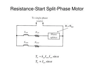
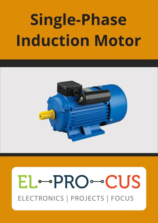
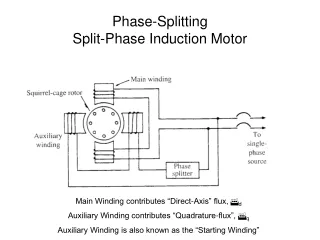
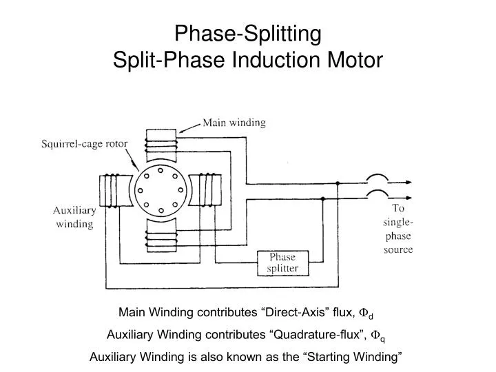
Phase-SplittingSplit-Phase Induction Motor Main Winding contributes “Direct-Axis” flux, d Auxiliary Winding contributes “Quadrature-flux”, q Auxiliary Winding is also known as the “Starting Winding”
Purpose of the “Phase-Splitter” • Make the current in the Auxiliary Winding out of phase with the current in the Main Winding. • This results in the quadrature field and the main field being out of phase. • The locked-rotor torque will be given by
Example 6-1 • The main and auxiliary windings of a hypothetical 120 V, 60 Hz, split-phase motor have the following locked-rotor parameters: • Rmw=2.00 Ω Xmw=3.50 Ω • Raw=9.15 Ω Xaw=8.40 Ω • The motor is connected to a 120 V system. Determine
Example 6-1 continued • The locked-rotor current in each winding
Example 6-1 continued • The phase displacement angle between the main and auxiliary currents
Example 6-1 continued • The locked-rotor torque in terms of the machine constant
Example 6-1 continued • External resistance required in series with the auxiliary winding in order to obtain a 30 phase displacement between the currents in the two windings.
Example 6-1 continued • Phasor diagram for the new conditions
Example 6-1 continued • Locked-rotor torque for the condition in d
Example 6-1 continued • % increase in locked-rotor torque due to the adding of additional resistance