Download
1 / 1
20 likes | 177 Views
Dr. Kirti Ghia, Project Mentor School of Aerospace Systems. Michael Cline Mechanical Engineering – ACCEND Class of 2014. Brandon Mullen Aerospace Engineering Class of 2016. NSF Type 1 STEP Grant, Grant ID No.: DUE-0756921. 2. What is “flow control?”

E N D
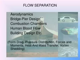
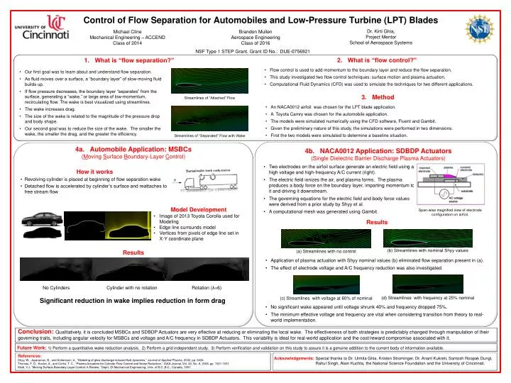
Dr. Kirti Ghia, Project Mentor School of Aerospace Systems Michael Cline Mechanical Engineering – ACCEND Class of 2014 Brandon Mullen Aerospace Engineering Class of 2016 NSF Type 1 STEP Grant, Grant ID No.: DUE-0756921 • 2. What is “flow control?” • Flow control is used to add momentum to the boundary layer and reduce the flow separation. • This study investigated two flow control techniques: surface motion and plasma actuation. • Computational Fluid Dynamics (CFD) was used to simulate the techniques for two different applications. • What is “flow separation?” • Our first goal was to learn about and understand flow separation. • As fluid moves over a surface, a “boundary layer” of slow-moving fluid builds up. • If flow pressure decreases, the boundary layer “separates” from the surface, generating a “wake,” or large area of low-momentum, recirculating flow. The wake is best visualized using streamlines. • The wake increases drag. • The size of the wake is related to the magnitude of the pressure drop and body shape. • Our second goal was to reduce the size of the wake. The smaller the wake, the smaller the drag, and the greater the efficiency. • 3. Method • An NACA0012 airfoil was chosen for the LPT blade application. • A Toyota Camry was chosen for the automobile application. • The models were simulated numerically using the CFD software, Fluent and Gambit. • Given the preliminary nature of this study, the simulations were performed in two dimensions. • First the two models were simulated to determine a baseline situation. Streamlines of “Attached” Flow Control of Flow Separation for Automobiles and Low-Pressure Turbine (LPT) Blades Streamlines of “Separated” Flow with Wake 4a. Automobile Application: MSBCs (Moving Surface Boundary-Layer Control) 4b. NACA0012 Application: SDBDP Actuators (Single Dielectric Barrier Discharge Plasma Actuators) • Two electrodes on the airfoil surface generate an electric field using a high voltage and high-frequency A/C current (right). • The electric field ionizes the air, and plasma forms. The plasma produces a body force on the boundary layer, imparting momentum to it and driving it downstream. • The governing equations for the electric field and body force values were derived from a prior study by Shyy et al. • A computational mesh was generated using Gambit. • How it works • Revolving cylinder is placed at beginning of flow separation wake • Detached flow is accelerated by cylinder’s surface and reattaches to free stream flow • Model Development • Image of 2013 Toyota Corolla used for Modeling • Edge line surrounds model • Vertices from pixels of edge line set in X-Y coordinate plane • Span-wise magnified view of electrode configuration on airfoil. Results • (b) Streamlines with nominal Shyy values • (a) Streamlines with no control Results • Application of plasma actuation with Shyy nominal values (b) eliminated flow separation present in (a). • The effect of electrode voltage and A/C frequency reduction was also investigated. No Cylinders Cylinder with no rotation Rotation (λ=6) • (d) Streamlines with frequency at 25% nominal • (c) Streamlines with voltage at 60% of nominal Significant reduction in wake implies reduction in form drag • No significant wake appeared until voltage shrunk 40% and frequency dropped 75%. • The minimum effective voltage and frequency are vital when considering transition from theory to real-world implementation. • Conclusion: Qualitatively, it is concluded MSBCs and SDBDP Actuators are very effective at reducing or eliminating the local wake. The effectiveness of both strategies is predictably changed through manipulation of their governing traits, including angular velocity for MSBCs and voltage and A/C frequency in SDBDP Actuators. This variability is ideal for real-world application and the cost/reward compromise associated with it. • Future Work: 1) Perform a quantitative wake reduction analysis. 2) Perform a grid independent study. 3) Perform verification and validation on this study to assure it is a genuine addition to the current body of information available. References: Shyy, W., Jayaraman, B., and Andersson, A., “Modeling of glow discharge-induced fluid dynamics,” Journal of Applied Physics, 2002, pp. 6434. Thomas, F. O., Kozlov, A., and Corke, T. C., “Plasma Actuators for Cylinder Flow Control and Noise Reduction,” AIAA Journal, Vol. 46, No. 8, 2008, pp. 1921-1931. Modi, V.J. “Moving Surface Boundary Layer Control: A Review,” Deprt. Of Mechanical Engineering, Univ. of B.C.,B.C., Canada, 1997. • Acknowledgements:Special thanks to Dr. Urmila Ghia, Kristen Strominger, Dr. Anant Kukreti, Santosh Roopak Dungi, Rahul Singh, Alain Kuchta, the National Science Foundation and the University of Cincinnati.