Download
1 / 58
580 likes | 746 Views
VLANs. LAN Switching and Wireless – Chapter 3 Modified by Michael W Haines. 04/28/2009. Objectives. Explain the role of VLANs in a converged network. Explain the role of trunking VLANs in a converged network. Configure VLANs on the switches in a converged network topology.

E N D
VLANs LAN Switching and Wireless– Chapter 3 Modified by Michael W Haines 04/28/2009
Objectives • Explain the role of VLANs in a converged network. • Explain the role of trunking VLANs in a converged network. • Configure VLANs on the switches in a converged network topology. • Troubleshoot the common software or hardware misconfigurations associated with VLANs on switches in a converged network topology.
Introducing VLANs (Before VLANs) • Consider a small community college with student dorms and the faculty offices all in one building. • The figure shows the student computers in one LAN and the faculty computers in another LAN. • This works fine because each department is physically together, so it is easy to provide them with their network resources. • A year later, the college has grown and now has 3 buildings. • In the figure, student and faculty computers are spread out across three buildings. • The student dorms remain on the fifth floor and the faculty offices remain on the third floor. • How can the network accommodate the shared needs of the geographically separated departments? • Do you create a large LAN and wire each department together? • It would be great to group the people with the resources they use regardless of their geographic location, and it would make it easier to manage their specific security and bandwidth needs.
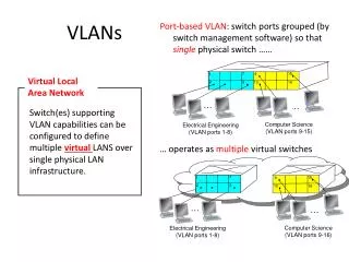
VLAN Overview • The solution for the community college is to use a networking technology called a virtual LAN (VLAN). • A VLAN allows a network administrator to create groups of logically networked devices that act as if they are on their own independent network, even if they share a common infrastructure with other VLANs. • Using VLANs, you can logically segment switched networks based on functions, departments, or project teams. • A VLAN is a logically separate IP subnetwork. • In the figure, one VLAN is created for students and another for faculty. • These VLANs allow the network administrator to implement access and security policies to particular groups of users. • For example, the faculty, but not the students, can be allowed access to e-learning management servers for developing online course materials.
VLAN Overview • For computers to communicate on the same VLAN, • Each must have an IP address and a subnet mask that is consistent for that VLAN. • The switch has to be configured with the VLAN • Each port in the VLAN must be assigned to the VLAN. • A switch port with a singular VLAN configured on it is called an access port. • Remember, just because two computers are physically connected to the same switch does not mean that they can communicate. • Devices on two separate networks and subnets must communicate via a router (Layer 3), whether or not VLANs are used.
Switch A Switch A Switch B Red VLAN Red VLAN Red VLAN Black VLAN Black VLAN Black VLAN Green VLAN Green VLAN Green VLAN VLAN Operations • Each logical VLAN is like a separate physical bridge • Management/HR Department (red) • Accounting Department (black) • Data Recovery & IT Department (green) • Each logical VLAN is like a separate physical bridge • VLANs can span across multiple switches
Benefits of a VLAN • The primary benefits of using VLANs are: • Security - Groups that have sensitive data are separated from the rest of the network. • Cost reduction - Cost savings result from less need for expensive network upgrades and more efficient use of existing bandwidth and uplinks. • Higher performance - Dividing flat Layer 2 networks into multiple logical workgroups (broadcast domains) reduces unnecessary traffic on the network. • Broadcast storm mitigation - Dividing a network into VLANs reduces the number of devices that may participate in a broadcast storm. • Improved IT staff efficiency - VLANs make it easier to manage the network. • When you provision a new switch, all the policies and procedures already configured for the particular VLAN are implemented when the ports are assigned. • Simpler project or application management - Having separate functions makes working with a specialized application easier, for example, an e-learning development platform for faculty.
2 VLAN ID Ranges • Normal Range VLANs • Identified by a VLAN ID between 1 and 1005. • IDs 1002 through 1005 are reserved for Token Ring and FDDI VLANs. • IDs 1 and 1002 to 1005 are automatically created and cannot be removed. • Configurations are stored within a VLAN database file, called vlan.dat. • The vlan.dat file is located in the flash memory. • The VLAN trunking protocol (VTP), can only learn normal range VLANs. • Extended Range VLANs • Enable service providers to extend their infrastructure to a greater number of customers. • Identified by a VLAN ID between 1006 and 4094. • Support fewer VLAN features. • Are saved in the running configuration file. • VTP does not learn extended range VLANs.
255 VLANs Configurable • Cisco Catalyst 2960 switch can support up to 255 normal range and extended range VLANs, • Although the number configured affects the performance of the switch hardware. Because an enterprise network may need a switch with a lot of ports, Cisco has developed enterprise-level switches that can be joined or stacked together to create a single switching unit consisting of nine separate switches. Each separate switch can have 48 ports, which totals 432 ports on a single switching unit. In this case, the 255 VLAN limit per single switch could be a constraint for some enterprise customers. You can have the number between 1 – 1005, but you can only use 255 of them.
Common VLAN Terminologies • Data VLAN • A data VLAN is a VLAN that is configured to carry only user-generated traffic. • A VLAN could carry voice traffic or manage traffic, but this traffic would not be part of a data VLAN. • It is common practice to separate voice and management traffic from data traffic. • A data VLAN is referred to as a user VLAN. • Default VLAN • All switch ports become a member of the default VLAN after the initial boot up of the switch. • The default VLAN for Cisco switches is VLAN 1. • VLAN 1 cannot be renamed and deleted. • Layer 2 control traffic, such as CDP and spanning tree protocol traffic, will always be associated with VLAN 1 - this cannot be changed. • It is a security best practice to change the default VLAN to a VLAN other than VLAN 1. • VLAN trunks support the transmission of traffic from more than one VLAN. • Black Hole VLAN – Dummy VLAN –Unused switch ports will be asign to the Black Hole Vlan
Common VLAN Terminologies • Native VLAN • An 802.1Q trunk port supports traffic coming from VLANs (tagged traffic) as well as traffic that does not come from a VLAN (untagged traffic). • The 802.1Q trunk port places untagged traffic on the native VLAN. • Native VLANs are set out in the IEEE 802.1Q specification to maintain backward compatibility with untagged traffic common to legacy LAN scenarios. • It is a best practice to use a VLAN other than VLAN 1 as the native VLAN. • Management VLAN • A management VLAN is any VLAN you configure to access the management capabilities of a switch. • You assign the management VLAN an IP address and subnet mask. • The out-of-the-box configuration of a Cisco switch has VLAN 1 as the default VLAN, the VLAN 1 would be a bad choice as the management VLAN;
Explaining 802.1Q Native VLANs • The purpose of the native VLAN is to allow frames not tagged with a VLAN ID to traverse the trunk link. • An 802.1Q native VLAN is defined as the following: • VLAN that a port is associated with when not in trunking operational mode • VLAN that is associated with untagged frames that are received on a switch port • VLAN to which Layer 2 frames are forwarded if received untagged on an 802.1Q trunk port • Compare this to ISL, in which no frame may be transported on the trunk link without encapsulation, and any unencapsulated frames received on a trunk port are immediately dropped.
Common VLAN Terminologies: Voice VLANs • VoIP traffic requires: • Assured bandwidth to ensure voice quality • Transmission priority over other types of network traffic • Ability to be routed around congested areas • Delay of less than 150 ms across the network • The details of how to configure a network to support VoIP are beyond the scope of the course, but it is useful to summarize how a voice VLAN works between a switch, a Cisco IP phone, and a computer. • In figure, VLAN 150 is designed to carry voice traffic. • The student computer PC5 is attached to the Cisco IP phone, and the phone is attached to switch S3. • PC5 is in VLAN 20, which is used for student data. • The F0/18 port on S3 is configured to be in voice mode • it will tell the phone to tag voice frames with VLAN 150. Data frames coming through the Cisco IP phone from PC5 are left untagged. • Data destined for PC5 coming from port F0/18 is tagged with VLAN 20 on the way to the phone, which strips the VLAN tag before the data is forwarded to PC5.
Common VLAN Terminologies: Voice VLANs • A Cisco Phone is a Switch • The Cisco IP Phone contains an integrated 3-port 10/100 switch. • Port 1 connects to the switch or other voice-over-IP (VoIP) device. • Port 2 is an internal 10/100 interface that carries the IP phone traffic. • Port 3 (access port) connects to a PC or other device. • The voice VLAN feature enables switch ports to carry IP voice traffic from an IP phone. • When the switch port has been configured with a voice VLAN, the link between the switch and the IP phone acts as a trunk to carry both the tagged voice traffic and untagged data traffic. • When the switch is connected to an IP Phone, the switch sends messages that instruct the attached IP phone to send voice traffic tagged with the voice VLAN ID 150. • The traffic from the PC attached to the IP Phone passes through the IP phone untagged. • Note: Communication between the switch and IP phone is facilitated by the CDP protocol. • Sample Configuration • The figure shows sample output. A discussion of the Cisco IOS commands are beyond the scope of this course, but you can see that the highlighted areas in the sample output show the F0/18 interface configured with a VLAN configured for data (VLAN 20) and a VLAN configured for voice (VLAN 150).
Network Traffic Types • Network Management and Control Traffic • Many different types of network management and control traffic can be present on the network, such as • Cisco Discovery Protocol (CDP) updates, • Simple Network Management Protocol (SNMP) traffic, • Remote Monitoring (RMON) traffic. • In a network configured with VLANs, it is strongly recommended to assign a VLAN other than VLAN 1 as the management VLAN. • IP Telephony Traffic • The types of IP telephony traffic are signaling traffic and voice traffic. • Signaling traffic is, responsible for call setup, progress, and teardown, and traverses the network end to end. • The other type of telephony traffic consists of data packets of the actual voice conversation. • voice traffic is associated with a voice VLAN.
Network Traffic Types • IP Multicast Traffic • IP multicast traffic is sent from a particular source address to a multicast group that is identified by a single IP and MAC destination-group address pair. • Examples of applications that generate this type of traffic are Cisco IP/TV broadcasts. • Multicast traffic can produce a large amount of data across the network. VLANs should be configured to ensure multicast traffic only goes to those user devices that use the service provided. • Routers must be configured to ensure that multicast traffic is forwarded to the network areas where it is requested. • Normal Data Traffic • Normal data traffic is related to file creation and storage, print services, e-mail database access, and other shared network applications that are common to business uses. • Data traffic should be associated with a data VLAN (other than VLAN 1), and • Scavenger Class Traffic • The Scavenger class is intended to provide less-than best-effort services to certain applications. • Applications assigned to this class have little or no contribution to the organizational objectives of the enterprise and are typically entertainment oriented in nature. • These include peer-to-peer media-sharing applications (KaZaa, Morpheus, Groekster, Napster, iMesh, and so on), gaming applications (Doom, Quake, Unreal Tournament, and so on), and any entertainment video applications.
VLAN Switch Port Modes • Switch ports are used for managing the physical interface and associated Layer 2 protocols. • They do not handle routing or bridging. • Switch ports belong to one or more VLANs. • A port can be configured to support these VLAN types: • Static VLAN - Ports on a switch are manually assigned to a VLAN. • Static VLANs are configured using the Cisco CLI. • This can also be accomplished with GUI management applications, such as the Cisco Network Assistant. • Dynamic VLAN - This mode is not widely used in production networks. A dynamic port VLAN membership is configured using a special server called a VLAN Membership Policy Server (VMPS). With the VMPS, you assign switch ports to VLANs dynamically, based on the source MAC address of the device connected to the port. • Voice VLAN - A port is configured to be in voice mode so that it can support an IP phone attached to it. • Next Page
VLAN operation – Dynamic VLAN • Dynamic VLANs, as opposed to Static VLANs, do not require the administrator to individually configure each port, but instead, a central server called the VMPS (VLAN Member Policy Server). The VMPS is used to handle the on-the-spot port configuration of every switch participating on the VLAN network. • The VMPS server contains a database of all workstation MAC addresses, along with the associated VLAN the MAC address belongs to. This way, we essentially have a VLAN-to-MAC address mapping More explanation on the next slide
Dynamic VLAN VMPS opens a UDP socket to communicate and listen to client Catalyst requests. • When the VMPS server receives a valid request from a client Catalyst, it searches its database for a MAC address-to-VLAN mapping. • If the assigned VLAN is restricted to a group of ports, VMPS verifies the requesting port against this group. • If the VLAN is allowed on the port, the VLAN name is returned to the client. • If the VLAN is not allowed on the port and VMPS is not in secure mode, the host receives an "access-denied" response. If VMPS is in secure mode, the port is shut down. • If a VLAN in the database does not match the current VLAN on the port and active hosts are on the port, VMPS sends an access-denied or a port-shutdown response based on the secure mode of the VMPS. • You can configure a fallback VLAN name. If you connect a device with a MAC address that is not in the database, VMPS sends the fallback VLAN name to the client. If you do not configure a fallback VLAN and the MAC address does not exist in the database, VMPS sends an access-denied response. If VMPS is in secure mode, it sends a port-shutdown response.
Dynamic VLAN Setup for multiple switches http://www.cisco.com/en/US/products/hw/switches/ps4324/products_configuration_guide_chapter09186a008011c8d3.html#26751 When you enable VMPS, a MAC address-to-VLAN mapping database downloads from a Trivial File Transfer Protocol (TFTP) server and VMPS begins to accept client requests. If you reset or power cycle the Catalyst 5000, 4000, 900, 3500, or 6000 Series Switch, the VMPS database downloads from the TFTP server automatically and VMPS is reenabled. • With a VLAN Management Policy Server (VMPS), you can assign switch ports to VLANs dynamically, based on the source MAC address of the device connected to the port. • When you move a host from a port on one switch in the network to a port on another switch in the network, the switch assigns the new port to the proper VLAN for that host dynamically.
VLAN Switch Port Modes • Voice VLAN - A port is configured to be in voice mode so that it can support an IP phone attached. • Before you configure a voice VLAN on the port, you need to first configure a VLAN for voice and a VLAN for data. • In the figure, VLAN 150 is the voice VLAN, and VLAN 20 is the data VLAN. • It is assumed that the network has been configured to ensure that voice traffic can be transmitted with a priority status over the network. • The figure shows the Voice Mode Example: • The configuration command mls qos trust cos ensures that voice traffic is identified as priority traffic. • Remember that the entire network must be set up to prioritize voice traffic. You cannot just configure the port with this command. • The switchport voice VLAN 150 command identifies VLAN 150 as the voice VLAN. • The switchport access VLAN 20 command configures VLAN 20 as the access mode (data) VLAN. • For more details about voice VLAN: http://www.cisco.com/en/US/products/ps6406/products_configuration_guide_chapter09186a008081d9a6.html#wp1050913.
Controlling Broadcast Domain with VLANs • Network Without VLANS • In normal operation, when a switch receives a broadcast frame on one of its ports, it forwards the frame out all other ports on the switch. • In the figure, the entire network is configured in the same subnet, 172.17.40.0/24. As a result, when the faculty computer, PC1, sends out a broadcast frame, the entire network receives it. • Network with VLANs • In the figure, the network has been segmented into two VLANs: Faculty as VLAN 10 and Student as VLAN 20. • When the broadcast frame is sent from the faculty computer, PC1, to switch S2, the switch forwards that broadcast frame only to those switch ports configured to support VLAN 10. • In the figure, the ports that make up the connection between switches S2 and S1 (ports F0/1) and between S1 and S3 (ports F0/3) have been configured to support all the VLANs in the network. This connection is called a trunk. You will learn more about trunks later in this chapter.
Intra-VLAN and inter-VLAN Communication • Controlling Broadcast Domains with Switches and Routers • Breaking up a big broadcast domain into several smaller ones reduces broadcast traffic and improves network performance. • Breaking up broadcast domains can be performed either with VLANs (on switches) or with routers. • A router is needed any time devices on different Layer 3 networks need to communicate, regardless whether VLANs are used. • Intra-VLAN Communication • In the figure, PC1, wants to communicate with another device, PC4. PC1 and PC4 are both in VLAN 10. Communicating with a device in the same VLAN is called intra-VLAN communication: • Step 1. PC1 in VLAN 10 sends its ARP request frame (broadcast) to switch S2. Switches S2 and S1 send the ARP request frame out all ports on VLAN 10. Switch S3 sends the ARP request out port F0/11 to PC4 on VLAN 10. • Step 2. The switches in the network forward the ARP reply frame (unicast) back to PC1. PC1 receives the reply which contains the MAC address of PC4. • Step 3. PC1 now has the destination MAC address of PC4 and uses this to create a unicast frame with PC4's MAC address as the destination. Switches S2, S1 and S3 deliver the frame to PC4.
Intra-VLAN and inter-VLAN Communication • Inter-VLAN Communication • In the figure, PC1 in VLAN 10 wants to communicate with PC5 in VLAN 20. Communicating with a device in another VLAN is called inter-VLAN communication. • Step 1. PC1 in VLAN 10 wants to communicate with PC5 in VLAN 20. PC1 sends an ARP request frame for the MAC address of the default gateway R1. • Step 2. The router R1 replies with an ARP reply frame from its interface configured on VLAN 10. • All switches forward the ARP reply frame and PC1 receives it. The ARP reply contains the MAC address of the default gateway. • Step 3. PC1 then creates an Ethernet frame with the MAC address of the Default Gateway. The frame is sent from switch S2 to S1. • Step 4. The router R1 sends an ARP request frame on VLAN 20 to determine the MAC address of PC5. Switches, S1, S2, S3, broadcast the ARP request frame out ports configured for VLAN 20. PC5 on VLAN 20 receives the ARP request frame from router R1. • Step 5. PC5 on VLAN 20 sends an ARP reply frame to switch S3. Switches S3 and S1 forward the ARP reply frame to router R1 with the destination MAC address of interface F0/2 on router R1. • Step 6. Router R1 sends the frame received from PC1 though S1 and S3 to PC5 (on vlan 20).
Layer 3 Forwarding • VLANs and Layer 3 Forwarding • The icon that represents a Layer 3 switch is shown. • A Layer 3 switch has the ability to route transmissions between VLANs. The procedure is the same as described for the inter-VLAN communication using a separate router. • SVI • Switch virtual interface (SVI) is a logical interface configured for a specific VLAN. You need to configure an SVI for a VLAN if you want to route between VLANs. • PC1 wants to communicate with PC5: • Step 1. PC1 sends an ARP request broadcast on VLAN10. S2 forwards the ARP request out all ports configured for VLAN 10. • Step 2. Switch S1 forwards the ARP request out all ports configured for VLAN 10, including the SVI for VLAN 10. Switch S3 forwards the ARP request out all ports configured for VLAN 10. • Step 3. The SVI for VLAN 10 in switch S1 knows the location of VLAN 20. The SVI for VLAN 10 in switch S1 sends an ARP reply back to PC1 with this information. • Step 4. PC1 sends data, destined for PC5, as a unicast frame through switch S2 to the SVI for VLAN 10 in switch S1. • Step 5. The SVI for VLAN 20 sends an ARP request broadcast out all switch ports configured for VLAN 20. Switch S3 sends that ARP request broadcast out all switch ports configured for VLAN 20. • Step 6. PC5 on VLAN 20 sends an ARP reply. Switch S3 sends that ARP reply to S1. • Step 7. The SVI for VLAN 20 forwards the data, sent from PC1, in a unicast frame to PC5 using the destination address it learned from the ARP reply in step 6.
VLAN Trunks • Definition of a VLAN Trunk • A trunk is a point-to-point link between one or more Ethernet switch interfaces and another networking device, such as a router or a switch. • Ethernet trunks carry the traffic of multiple VLANs over a single link. • A VLAN trunk allows you to extend the VLANs across an entire network. • Cisco supports IEEE 802.1Q for coordinating trunks on Fast Ethernet and Gigabit Ethernet interfaces. • [Tony] and inter-switch link (ISL), too • A VLAN trunk does not belong to a specific VLAN, rather it is a conduit for VLANs between switches and routers.
What Problem Does a Trunk Solve? 1 • In the figure 1, you see the standard topology used in this chapter, except instead of the VLAN trunk that you are used to seeing between switches S1 and S2, there is a separate link for each subnet. • There are four separate links connecting switches S1 and S2, leaving three fewer ports to allocate to end-user devices. • Each time a new subnetwork is considered, a new link is needed for each switch in the network. • In the figure 2, the network topology shows a VLAN trunk connecting switches S1 and S2 with a single physical link. 2
802.1Q Frame Tagging • 802.1Q Frame Tagging • Switches are layer 2 devices. They only use the Ethernet frame header information to forward packets. • The frame header does not contain information about which VLAN the frame should belong to. • When Ethernet frames are placed on a trunk they need additional information about the VLANs they belong to. • This header adds a tag to the original Ethernet frame specifying the VLAN for which the frame belongs to. • VLAN Tag Field Details • EtherType field • Set to the hexadecimal value of 0x8100. • Tag control information field • 3 bits of user priority - Used by the 802.1p standard, specifies how to provide expedited transmission of Layer 2 frames. • 1 bit of Canonical Format Identifier (CFI) - Enables Token Ring frames to be carried across Ethernet links easily. • 12 bits of VLAN ID (VID) - VLAN identification numbers; supports up to 4096 VLAN IDs. • FCS field • It recalculates the FCS values and inserts it into the frame.
Native VLANs and 802.1Q Trunking Tag • Tagged Frames on the Native VLAN • Some devices that support trunking tag native VLAN traffic as a default behavior. • Control traffic sent on the native VLAN should be untagged. • If an 802.1Q trunk port receives a tagged frame on the native VLAN, it drops the frame. • Consequently, when configuring a switch port on a Cisco switch, you need to configure them so that they do not send tagged frames on the native VLAN. • Untagged Frames on the Native VLAN • When a Cisco switch trunk port receives untagged frames it forwards those frames to the native VLAN. • The default native VLAN is VLAN 1. When you configure an 802.1Q trunk port, a default Port VLAN ID (PVID) is assigned the native VLAN ID. All untagged traffic coming in or out of the 802.1Q port is forwarded based on the PVID value. • In this example, VLAN 99 will be configured as the native VLAN on port F0/1. • Using the show interfaces interface-id switchport command, you can quickly verify that you have correctly reconfigured the native VLAN from VLAN 1 to VLAN 99.
A Trunk in Action • 3) Switch S1 reads the VLAN ID on the frames and broadcasts them to each port configured to support VLAN 10 and VLAN 30. 1) In the figure, PC1 on VLAN 10 and PC3 on VLAN 30 send broadcast frames to switch S2. 2) Switch S2 tags these frames with the appropriate VLAN ID and then forwards the frames over the trunk to switch S1. 4) Switch S3 receives these frames and strips off the VLAN IDs and forwards them as untagged frames to PC4 on VLAN 10 and PC6 on VLAN 30.
Trunking Mode: ISL and Dot1Q • Some Cisco switch can be configured to support 2 types of trunk ports, • IEEE 802.1Q • ISL, • Today only 802.1Q is used. However, legacy networks may still use ISL, and it is useful to learn about each type of trunk port. • An 802.1Q trunk port supports simultaneous tagged and untagged traffic. • An 802.1Q trunk port is assigned a default PVID, and all untagged traffic travels on the port default PVID. • All untagged traffic and tagged traffic with a null VLAN ID are assumed to belong to the port default PVID. • A packet with a VLAN ID equal to the outgoing port default PVID is sent untagged. All other traffic is sent with a VLAN tag. • In an ISL trunk port, all received packets are expected to be encapsulated with an ISL header, and all transmitted packets are sent with an ISL header. • Native (non-tagged) frames received from an ISL trunk port are dropped. • ISL is no longer a recommended trunk port mode, and it is not supported on a number of Cisco switches.
A Closer look at VLAN Tagging ISL • 802.1Q is recommended by Cisco and is used with multi-vendor switches. • Caution: Some older Cisco switches will only do ISL while some new Cisco switches will only do 802.1Q. • Many of Cisco switches do not support ISL any more. IEEE 802.1Q
Trunking Mode: DTP • Dynamic Trunking Protocol (DTP) is a Cisco proprietary protocol. Switches from other vendors do not support DTP. • DTP is automatically enabled on a switch port when certain trunking modes are configured on the switch port. • DTP manages trunk negotiation only if the port on the other switch is configured in a trunk mode that supports DTP. DTP supports both ISL and 802.1Q trunks. • Cisco old switches and routers do not support DTP. • The following provides a brief description of the available trunking modes and how DTP is implemented in each. • On (default) • The switch port periodically sends DTP frames, called advertisements, to the remote port. The command used is switchport mode trunk. The local switch port advertises to the remote port that it is dynamically changing to a trunking state. • Dynamic auto • The switch port periodically sends DTP frames to the remote port. The command used is switchport mode dynamic auto. The local switch port advertises to the remote switch port that it is able to trunk but does not request to go to the trunking state. • Dynamic desirable • DTP frames are sent periodically to the remote port. The command used is switchport mode dynamic desirable. The local switch port advertises to the remote switch port that it is able to trunk and asks the remote switch port to go to the trunking state.
Trunking Mode: DTP • Turn off DTP • You can turn off DTP for the trunk so that the local port does not send out DTP frames to the remote port. Use the command switchport nonegotiate. The local port is then considered to be in an unconditional trunking state. • A Trunk Mode Example • In the figure 1, the F0/1 ports on switches S1 and S2 are configured with trunk mode on. The F0/3 ports on switches S1 and S3 are configured to be in auto trunk mode. • In the figure 2, the link between switches S1 and S2 becomes a trunk because the F0/1 ports on switches S1 and S2 are configured to ignore all DTP advertisements and come up and stay in trunk port mode. • In the figure 2 , the F0/3 ports on switches S1 and S3 are set to auto, so they negotiate to be in the default state, the access (non-trunk) mode state. • Note: The default switchport mode for an interface on a Catalyst 2950 switch is dynamic desirable, but the default switchport mode for an interface on a Catalyst 2960 switch is dynamic auto. If S1 and S3 were Catalyst 2950 switches with interface F0/3 in default switchport mode, the link between S1 and S3 would become an active trunk.
Describing Trunking Configuration Commands (cont.) • This Cisco proprietary protocol can determine an operational trunking mode and protocol on a switch port when it is connected to another device that is also capable of dynamic trunk negotiation. • DTP mode can be configured to turn the protocol off or to instruct it to negotiate a trunk link only under certain conditions.
Describing Trunking Configuration Commands (cont.) • The default DTP mode is Cisco IOS and platform dependent. To determine the current DTP mode, use the show dtp interface command. • Note that this command is not available on Catalyst 2950 and 3550 switches, but is available on Catalyst 2960 and 3560 switches. • General best practice is to set the interface to trunk and nonegotiate when a trunk link is required. DTP should be turned off on links where trunking is not intended.
Trunking implementation (cont.) • Before attempting to configure a VLAN trunk on a port, determine what encapsulation the port can support. This can be done using the show interface fastethernet [slot/port_num] capabilities command. 3550 3550 * This commands does not exist in 2900XL switch.
Trunking implementation • Cisco Catalyst 2950 only supports 802.1Q. • Therefore, it does not gives you the option to setup other encapsulation type. 2950 • The following is the command that I am looking for, but it does not exist. 2950 switch only runs dot1q • ALSwitch(config)#switchport trunk encapsulation isl • ALSwitch(config)#switchport trunk encapsulation dot1q • Another command to show this switch only runs dot1q 2950
Dynamic Trunking Protocol (DTP) • Dynamic Trunking Protocol (DTP), a Cisco proprietary protocol in the VLAN group, is for negotiating trunking on a link between two devices and for negotiating the type of trunking encapsulation (802.1Q) to be used Cisco 2950 Catalyst switch
Identifying the modes for Dynamic Trunking Protocol http://www.cisco.com/warp/public/793/lan_switching/2.html
See how DTP works No cable is connected to the switch. • By default all the port are access port, but they are trunk desirable. • You don’t have to configure trunking on either end of the 2950. It will automatically become a trunk port when you have a crossover cable interconnect between 2 of 2950 switches. • 2950 DTP Connect a crossover to port 1 from the other 2950 switch Automatically a trunk port is established. Port 1 is deleted from vlan 1 and become a trunk port.
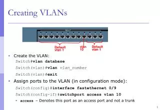
Step 1: Configure a VLAN • There are two different modes for configuring VLANs on a Cisco Catalyst switch, database configuration mode and global configuration mode. • Although the Cisco documentation mentions VLAN database configuration mode, it is being phased out in favor of VLAN global configuration mode. • You will configure VLANs with IDs in the normal range. • The normal range includes IDs 1 to 1001. • The extended range consists of IDs 1006 to 4094. • VLAN 1 and 1002 to 1005 are reserved ID numbers. • When you configure normal range VLANs, the configuration details are stored automatically in flash memory on the switch in a file called vlan.dat. • The figure shows how the student VLAN, VLAN 20, is configured on switch S1. • The figure shows an example of using the show vlan brief command to display the contents of the vlan.dat file. • In addition to entering a single VLAN ID, you can enter a series of VLAN IDs separated by commas, or a range of VLAN IDs separated by hyphens using the vlan vlan-id command, for example: switch(config)#vlan 100,102,105-107.
Step 2: Assign a Switch Port • After you have created a VLAN, assign one or more ports to the VLAN. When you manually assign a switch port to a VLAN, it is known as a static access port. • A static access port can belong to only one VLAN at a time. • Example shows how the student VLAN, VLAN 20, is statically assigned to port F0/18 on switch S1. • Port F0/18 has been assigned to VLAN 20 so the student computer, PC2, is in VLAN 20. • When VLAN 20 is configured on other switches, the network administrator knows to configure the other student computers to be in the same subnet as PC2: 172.17.20.0 /24. • Confirm the configuration using the show vlan brief command displays the contents of the vlan.dat file.
Step 3: Verify VLANs and Port Memberships • In this example, you can see that the show vlan name student command does not produce very readable output. • The show vlan summary command displays the count of all configured VLANs. • The show vlan brief command. • The show interface vlan command displays a lot of detail information. The key information appears on the second line, indicating that VLAN 20 is up. • The show interface fa 0/18 switchport command displays information that is useful to you. • The port F0/18 is assigned to VLAN 20 and that the native VLAN is VLAN 1.
Step 3: Manage Port Memberships • Reassign a Port to VLAN 1 • To reassign a port to VLAN 1, you can use the no switchport access vlan command in interface configuration mode. • Examine the output in the show vlan brief command that immediately follows. • Notice how VLAN 20 is still active. It has only been removed from interface F0/18. • In the show interfaces f0/18 switchport command, you can see that the access VLAN for interface F0/18 has been reset to VLAN 1 (It was on vlan 20). • Reassign the VLAN to Another Port • A static access port can only have one VLAN. • When you reassign a static access port to an existing VLAN, the VLAN is automatically removed from the previous port. • In the example, port F0/11is reassigned to VLAN 20 .
Step 3: Delete VLANs • The figure provides an example of using the global configuration command no vlan vlan-id to remove VLAN 20 from the system. • The show vlan brief command verifies that VLAN 20 is no longer in the vlan.dat file. • Alternatively, the entire vlan.dat file can be deleted using the command delete flash:vlan.dat from privileged EXEC mode. • After the switch is reloaded, the previously configured VLANs will no longer be present. • This effectively places the switch into is "factory default" concerning VLAN configurations. • Note: Before deleting a VLAN, be sure to first reassign all member ports to a different VLAN. Any ports that are not moved to an active VLAN are unable to communicate with other stations after you delete the VLAN.
Step 4: Configure an 802.1Q Trunk • To configure a trunk on a switch port, use the switchport mode trunk command. • When you enter trunk mode, the interface changes to permanent trunking mode, and the port enters into a DTP negotiation to convert the link into a trunk link even if the interface connecting to it does not agree to the change. • The Cisco IOS command syntax (switchport trunk native) to specify a native VLAN other than VLAN 1 is shown in the figure. • In the example, you configure VLAN 99 as the native VLAN. • The command syntax (switchport trunk allowed vlan & switchport trunk allow vlan add) used to allow a list of VLANs on the trunk is shown. • On this trunk port, allow VLANs 10, 20, and 30. • The example configures port F0/1 on switch S1 as the trunk port. It reconfigures the native VLAN as VLAN 99 and adds VLANs 10, 20, and 30 as allowed VLANs on port F0/1.
Step 5: Verify Trunk Configuration • The figure displays the configuration of switch port F0/1 on switch S1. The command used is the show interfaces interface-ID switchport command. • The first highlighted area shows that port F0/1 has its administrative mode set to Trunk - the port is in trunking mode. • The next highlighted area verifies that the native VLAN is VLAN 99, the management VLAN. • At the bottom of the output, the last highlighted area shows that the enabled trunking VLANs are VLANs 10, 20, and 30.
Step 5: Managing a Trunk Configuration • In the figure, the commands (no switchport trunk allowed vlan) to reset the allowed VLANs and (no switchport trunk native vlan) the native VLAN of the trunk to the default state. • The command (switchport mode access) to reset the switch port to an access port and, in effect, deleting the trunk port is also shown. • In the figure, the commands used to reset all trunking characteristics of a trunking interface to the default settings are highlighted in the sample output. • The show interfaces f0/1 switchport command reveals that the trunk has been reconfigured to a default state. • In the figure, the sample output shows the commands (switchport mode access) used to remove the trunk feature from the F0/1 switch port on switch S1. • The show interfaces f0/1 switchport command reveals that the F0/1 interface is now in static access mode.