Download
1 / 18
180 likes | 311 Views
Physical and Link Layers. CS144 Review Session 6 November 6 th , 2008 Roger Liao Based on slides by Ben Nham. Outline. Physical layer Encoding of signals Chips vs. bits Link layer Communication through shared medium Hubs vs. switches. Signaling bits on a link.

E N D
Physical and Link Layers CS144 Review Session 6 November 6th, 2008 Roger Liao Based on slides by Ben Nham
Outline • Physical layer • Encoding of signals • Chips vs. bits • Link layer • Communication through shared medium • Hubs vs. switches
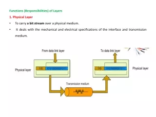
Signaling bits on a link • Most electrical and optical networks signal bits using two distinct voltage/power levels.
Coding schemes Multilevel encoding Frequency division multiplexing High speed links use a selection of complicated techniques to squeeze maximum data-rate from link Capacity – maximum data rate of a link
Manchester Encoding • Synchronous digital systems need a clock to trigger sampling of data • Manchester encoding allows us to encode the clock with the data stream • The preamble to the Ethernet frame is used to synchronize the sender clock with the receiver clock • In Manchester encoding: • Transmitter samples data on edge of clock (usually rising edge) • If we sample a 1, it is encoded by a rising edge • If we sample a 0, it is encoded by a falling edge
Manchester Encoding Question • Suppose a 10Mbps NIC sends into a link an infinite stream of zeros using Manchester encoding. The signal emerging from the adapter will have how many transitions per second? • 2 transitions per bit time • Bit times occur at clock frequency of 10MHz • Transitions occur at 20 MHz clk data encoding
Chips and Bits • Chips – 1’s and 0’s at physical layer • Bits – Actual data • Encoded for: • Clock encoding • Error detection • Error correction • Example • Straw man example 1 • Duplicate bits • Bits: 101 • Chips: 110011 • Now we can detect one bit errors (100011 – invalid!) • Straw man example 2 • Triplicate bits • Bits: 101 • Chips: 111000111 • Now we can correct one bit errors (101000111 – guess that the second bit is flipped) • In reality the physical layer does more efficient encodings but gets similar benefits
Arbitration of Shared Resources • General systems problem • I have a shared resource that only one person can use at a time • How do I arbitrate access to it? • Shared CPU, multiple processes need it – OS scheduler • Shared radio spectrum, multiple broadcasters – frequency division multiplexing • One Ethernet coax, multiple clients connected to it – CSMA/CD • Other ways of sharing a medium, e.g. Token Ring, Aloha, etc. in book
CSMA/CD in the Classroom • We are students sharing the air in this room, and develop the following protocol to arbitrate access to it: • Before I talk, I see if anyone else is talking • If anyone else is talking, don’t talk • If no one else is talking, start talking • If I start talking and sense that someone else has started talking, stop talking, and start talking some random time that increases exponentially to hope that no one is talking then
CSMA/CD in Ethernet • We are nodes sharing this Ethernet wire, and develop the following protocol to arbitrate access to it: • Before I send, I sense the wire to see if anyone else is sending • If anyone else is sending, don’t send • If no one else is sending, start sending • If I start sending and sense that someone else has started sending, stop sending, and start sending after waiting some random time that increases exponentially, to hope that no one is sending then • This is why CSMA/CD is known as an “exponential backoff” algorithm
t=PROP-- t=PROP- t=PROP t=2PROP- CSMA/CD Network Size Restriction To ensure that a packet is transmitted without a collision, a host must be able to detect a collision before it finishes transmitting a packet. A “Line is idle” “Line is idle” B t=0 PROP PROP Events: t=0: Host A starts transmitting a packet. t=PROP--: Just before the first bit reaches Host B, Host B senses the line to be idle and starts to transmit a packet. t=PROP-: A collision takes place near Host B. t=PROP: Host B receives data whilst transmitting, and so detects the collision.t=2PROP-: Host A receives data whilst transmitting, and so detects the collision. Credit: CS244a Handout 10
Length Limitation of CSMA/CD • There is a minimum size frame needed to be able to detect collisions: • Transmission Delay > 2 * Propagation Delay • Transmission Delay = MinSize / TransferRate • MinSize = TransferRate * 2 * Propagation Delay • Longer wire = larger prop delay = larger MinSize • Faster transfer rate = larger MinSize • Serious problem with Gigabit Ethernet and higher • Punt problem by saying that everyone is using switched networks anyway and not going to get collisions
Routers, Switches, and Hubs • Routers are network layer devices • Modify IP datagram (decrement TTL) • Hosts and other routers must be aware of them • Switches and hubs are link layer devices • Only care about frames, don’t modify IP datagram • Transparent to network
Hubs • Operate as a repeater • Broadcast an incoming frame to all ports, except for the ingress port • Like having a longer Ethernet cable that all the hosts tap into • All ports are on single collision domain! • Advantages: simple, restores signal, potentially fast since we don’t have to buffer or examine frame • Disadvantages: poor bandwidth due to collisions
Hub Question 1 • A 10-port hub is connected to 10 hosts using gigabit links. What is the maximum aggregate transfer rate of data flowing through this network? • All ports are part of the same collision domain--only one device can send at a time • Therefore, peak bandwidth is one gigabit
Hub Question 2 • Recall that 100Mbps Ethernet restricts cable lengths to 100m. Suppose we want to connect two hosts which are 1000m apart. Can we use 10 100m cables with 9 hubs in series to accomplish this? • No. Since all ports are on same collision domain, max network diameter (1km) is too large to meet the TRANSP > 2 * PROP constraint of CSMA/CD • In reality, the IEEE standard limits number of hubs in series and specifies maximum network diameter
Switches • Must store and examine frame before forwarding • Simple learning protocol—no configuration • Given incoming frame (MACsrc, MACdst) on port x: • Add (MACsrc, x) to switch table • Look up port for MACdst for in switch table • If entry is there, forward frame to that port • Else, broadcast frame to all ports (except ingress port) • Runs spanning tree protocol to prevent loops • Collision domain is a single port—switch will make sure that the frame it sends out does not collide with another frame being sent on the same link
NAT Preview • Lab 5 is NAT • Implement subset of NAT requirements • Layered on top of sr • Means you will be on VNS again