Download
1 / 8
80 likes | 233 Views
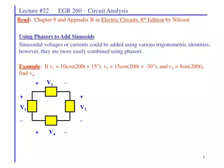
_. V 2. +. +. +. V 1. V 3. _. _. _. +. V 4. Lecture #22 EGR 260 – Circuit Analysis. Read : Chapter 9 and Appendix B in Electric Circuits, 8 th Edition by Nilsson. Using Phasors to Add Sinusoids

E N D
_ V2 + + + V1 V3 _ _ _ + V4 Lecture #22 EGR 260 – Circuit Analysis Read: Chapter 9 and Appendix B in Electric Circuits, 8th Edition by Nilsson Using Phasors to Add Sinusoids Sinusoidal voltages or currents could be added using various trigonometric identities; however, they are more easily combined using phasors. Example: If v1 = 10cos(200t + 15), v2 = 15cos(200t + -30), and v3 = 8sin(200t), find v4.
Lecture #22 EGR 260 – Circuit Analysis sin(wt) or cos(wt)? Since phasor analysis is used to calculate results that are relative to the sources, it generally doesn’t matter whether the sinusoidal source is expressed using sin(wt) or cos(wt). If the sources are expressed using sin(wt), then the results will also be in terms of sin(wt) and if the sources are expressed using cos(wt), then the results will also be in terms of cos(wt). However, the approach for a given circuit containing multiple sources must be consistent – either using cos(wt) or sin(wt). • Review of DC Circuit Analysis Techniques • Analyzing AC circuits is very similar to analyzing DC resistive circuits. Several examples are presented below which will also serve to review many DC analysis techniques, including: • Source transformations • Mesh equations • Node equations • Superposition • Thevenin’s and Norton’s theorems • Maximum Power Transfer theorem
Lecture #22 EGR 260 – Circuit Analysis • Source transformations • A phasor voltage source with a series impedance may be transformed into a phasor current source with a parallel impedance as illustrated below. The two sources are identical as far as the load is concerned. • Notes: • Not all sources can be transformed. Discuss. • The two sources are not equivalent internally. For example, the voltage across • Zs is not equivalent to the voltage across Zp. • Dependent sources can be transformed. Converting a real current source to a real voltage source: Converting a real voltage source to a real current source:
Lecture #22 EGR 260 – Circuit Analysis Example: Solve for the voltage V using source transformations.
Lecture #22 EGR 260 – Circuit Analysis Mesh equations: Example: Solve for the voltage V using mesh equations.
Lecture #22 EGR 260 – Circuit Analysis Node equations: Example: Solve for the current i(t) using node equations.
Lecture #22 EGR 260 – Circuit Analysis • Superposition: • Superposition can be used to analyze multiple-source AC circuits in a manner very similar to analyzing DC circuits. However, there are two special cases where it is highly recommended that superposition be used: • Circuits that include sources at two or more different frequencies • Circuits that include both DC and AC sources (Note: you could think of DC • sources as acting like AC sources with w = 0.) Example 1 (sources with different frequencies): Solve for the voltage V using superposition.
Lecture #22 EGR 260 – Circuit Analysis Example 2 (AC and DC sources): Solve for the voltage V using superposition.