Download

1 / 81
820 likes | 1.03k Views
Chapter 14 Operational Amplifiers. Chapter 14 Operational Amplifiers. List the characteristics of ideal op amps. 2 . Identify negative feedback in op-amp circuits. 3 . Analyze ideal op-amp circuits that have negative feedback using the summing-point constraint.

E N D
Chapter 14 Operational Amplifiers • List the characteristics of ideal op amps. • 2. Identify negative feedback in op-amp circuits. • 3. Analyze ideal op-amp circuits that have negative • feedback using the summing-point constraint.
4. Select op-amp circuit configurations suitable for various applications. 5. Design useful circuits using op amps. 6. Identify practical op-amp limitations and recognize potential inaccuracies in instrumentation applications. 7. Work with instrumentation amplifiers. 8. Apply integrators, differentiators, and active filters.
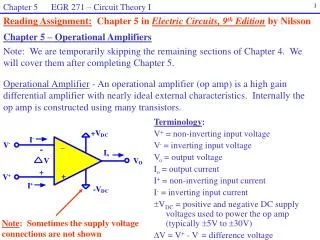
The input signal of a differential amplifier consists of a differential component and a common-mode component.
Characteristics of Ideal Op Amps • Infinite gain for the differential input signal • Zero gain for the common-mode input signal • Infinite input impedances • Zero output impedance • Infinite bandwidth
SUMMING-POINT CONSTRAINT Operational amplifiers are almost always used with negative feedback, in which part of the output signal is returned to the input in opposition to the source signal.
In a negative feedback system, the ideal op-amp output voltage attains the value needed to force the differential input voltage and input current to zero. We call this fact the summing-point constraint.
Ideal op-amp circuits are analyzed by the following steps: • Verify that negative feedback is present. • 2. Assume that the differential input voltage and the input current of the op amp are forced to zero. (This is the summing-point constraint.)
3. Apply standard circuit-analysis principles, such as Kirchhoff’s laws and Ohm’s law, to solve for the quantities of interest.
Positive Feedback With positive feedback, the op amp’s input and output voltages increase in magnitude until the output voltage reaches one of its extremes.
NONINVERTING AMPLIFIERS Under the ideal-op-amp assumption, the non- inverting amplifier is an ideal voltage amplifier having infinite input resistance and zero output resistance.
DESIGN OF SIMPLE AMPLIFIERS Amplifier design using op amps mainly consists of selecting a suitable circuit configuration and values for the feedback resistors.
If the resistances are too small, an impractical amount of current and power will be needed to operate the amplifier.
Very large resistance may be unstable in value and lead to stray coupling of undesired signals.
OP-AMP IMPERFECTIONS IN THE LINEAR RANGEOF OPERATION Real op amps have several categories of imperfections compared to ideal op amps. Real op amps have finite input impedance and nonzero output impedance.
NONLINEAR LIMITATIONS The output voltage of a real op amp is limited to the range between certain limits that depend on the internal design of the op amp. When the output voltage tries to exceed these limits, clipping occurs.
The output current range of a real op amp is limited. If an input signal is sufficiently large that the output current would be driven beyond these limits, clipping occurs.