Download
1 / 17
590 likes | 1.64k Views
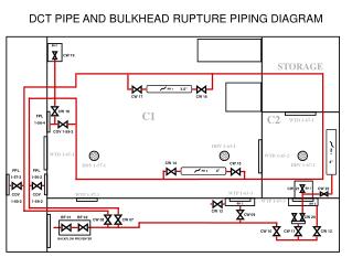
Hydrogen System – Piping and Instrumentation Diagram. Hydrogen System P&ID. Gas Panel. Helium Store. Venting. Vac. Pumps. Cryostat. Heater/ Chiller Unit. Hydrogen Bottle. Line Types and Colour Coding.

E N D
Hydrogen System P&ID Gas Panel Helium Store Venting Vac. Pumps Cryostat Heater/ Chiller Unit Hydrogen Bottle
Line Types and Colour Coding Note: This scheme is based on operating the system with Hydrogen rather than Helium.
Nomenclature • HA prefix used throughout to indicate Hydrogen System A • Pipelines • G or L prefix indicates whether line will contain gas or liquid during normal operation with cryo-cooler running. • Pipe size specified according to I.D. or DN standard.
Nomenclature (2) • Valves • All uniquely numbered • PV – Pneumatic Valve • CV – Control Valve • HV – Hand Valve • BD – Bursting Disc • RV – Relief Valve • Sized by DN standard • Set pressure shown for relief valves
Nomenclature (3) • Instrumentation • PG/VG – Pressure/Vacuum Gauge • LS – Level Sensor • TS – Temperature Sensor • HD – Hydrogen Detector • FM – Flow Meter • VP - Vacuum Pump
Gas Panel and Hood Extraction Hood Fill/Purge Valves Hydride Bed Buffer Volume Absorber Relief Valves Cryostat Relief Valves
Hydride Bed • Supplier: TREIBACHER INDUSTRIE AG • The nominal figures for the absorption temperature is -10°C and +20°C for the evolution temperature. • Heat Transfer Medium - Water / glycolMH • Weight: 120 kg • Tank Structure A hull with 7 inter-connected stainless-steel storage cylinders , each with internal coil for cooling/heating . • Dimensions Ø370 mm × L1500 mm (not including attachments), horizontal position • Tank Total Weight 260-280 kg • Operating Conditions: • Charging Gas Component Hydrogen of 99.99% purity • Charging Gas Pressure 1.2-1.7 bar abs • Hydrogen Charging Rate Max 70 NL/min • Discharging Gas Pressure 1.0-7.0 bar abs
Fill/Purge Valves • Pneumatically actuated valves • Arrow indicates position on failure
Valve Types • Ball Valves • Pneumatically actuated • Spring Return Actuators ensure valve returns to default position on failure • Control Valves • Pneumatically Actuated • Large range on throttling • Suitable for use with hydrogen
Relief Valves • Tyco (AG Series 90) Relief Valves • Pilot valves – quick acting • 3% tolerance on set pressure • Closes at 95% of set pressure • Response time is <0.5s • BS&B Low Pressure Reverse Buckling Disc • ±5% tolerance on burst pressure • Vacuum/back pressure resistant • Hand Valves can be locked off as necessary
Instrumentation • Temperature Sensors • Platinum Resistance • Fast response time (<0.5s) • Level Sensors • AMI Capacitance Level Transmitter • Useable with Hydrogen • Pressure and Vacuum Gauges • Leybold can supply capacitance vacuum gauges, which are safe for use with hydrogen. • Explosion proof pressure transducers available from Honeywell Temperature sensors Pressure Transducers Level Sensors
Cryostat Cryocooler Helium Jacketing on Pipes Compressor Pressure Transducers Level Sensors Pre-cooling loops Electrical heating of base plate
Vacuum System • 2 Elements • Purging Pump • for H2 system • Cryostat Vacuum
Vacuum System TRIVAC D40B • Proposal received from Leybold based on combination of rotary vane and turbo-molecular pumps • TRIVAC D40B for hydrogen system purging pump (VP1) • Special Pumpset with active control suggested for cryostat vacuum (VP2) • D25BCS backing pump • Turbo-molecular TMP151C to achieve high vacuum (10-3 mbar) • Both pumps can be operated with purge gas (e.g. He) if pressure rises (indicating a leak) TRIVAC D25BCS TMP151C
Venting • Hydrogen detectors in extraction hood, vent line and vacuum exhaust • 2 fans provide redundancy in venting from hood • Flame arrestors used throughout • Helium flow in vent line to dilute leaks Whessoe – Varec Flame Arrestor