Download
1 / 34
360 likes | 729 Views
http://aries.ucsd.edu/LASERLAB. Particulate Formation in Laser Plasma. M. S. Tillack, S. S. Harilal, C. V. Bindhu and D. Blair Center for Energy Research and Mechanical and Aerospace Engineering Department Jacobs School of Engineering. 2003 Simposio en Fisica de Materiales

E N D
http://aries.ucsd.edu/LASERLAB Particulate Formation in Laser Plasma M. S. Tillack, S. S. Harilal, C. V. Bindhu and D. Blair Center for Energy Research and Mechanical and Aerospace Engineering Department Jacobs School of Engineering 2003 Simposio en Fisica de Materiales Centro de Ciencias de Materia Condensada Universidad National Autónoma de México 24 January 2003
Laser plasmas have numerous applications in science and industry • Micromachining • Thin film deposition • Cluster production • Nanotube production • Surface modification • Surface cleaning • Elemental analysis • X-ray laser • Photolithography • Medicine • Inertial fusion energy
Problems in micromachining are caused by workpiece & equipment contamination Contaminated surface After cleaning Laser ink-jet printer head before and after cleaning (courtesy of HP) Laser entrance window on our ablation chamber
Use of lasers in thin film deposition (PLD) is also limited by a lack of control over particulate • Advantages • Almost any material • Doesn’t require very low pressures • Reactive deposition possible • Multilayer epitaxial films • Problems to be addressed • Particulates • Quality of films depends on deposition conditions – Detailed study of plume dynamics is necessary • Lack of adequate theory
Control of nanotube and nanoparticle fabrication requires a better understanding of the production mechanisms Schematic of nanotube synthesis (D. B. Geohegan, ORNL) • Understanding why laser ablation produces such high nanotube yields is a high priority • Species responsible for growth? • Spatial distribution and transport? • Growth times and rates?
A wide range of physics is involved: Understanding the mechanisms of particulate formation and methods to control them will enable greater use of lasers • Absorption, reflection • Heat transfer • Thermodynamics (phase change) • Plasma breakdown • Shock waves (gas) • Stress waves (solid) • Laser-plasma interactions • Gas dynamic expansion • Atomic & molecular processes • Others
Subtopics Experimental studies of the expansion dynamics of plumes interpenetrating into ambient gases Modeling and experiments on homogeneous nucleation and growth of clusters (surface ejection is another topic of interest to us!)
0.01Torr 0.1Torr 1Torr 10Torr 100Torr Experimental studies of the expansion dynamics of plumes interpenetrating into ambient gases
Lasers used in UCSD Laser Plasma and Laser-Matter Interactions Laboratory Spectra Physics 2-J, 8 ns Nd:YAG with harmonics 1064, 532, 355, 266 nm Lambda Physik 420 mJ, 20 ns multi-gas excimer laser (248 nm with KrF)
Experimental setup for studies of ablation plume dynamics Target : Al Laser Intensity : 5 GW cm-2 Ambient : 10-8 Torr – 100 Torr air
Approximate plasma parameters Electron Density: Measured using Stark broadening Initial ~ 1019cm-3 Falls very rapidly within 200 ns Follows ~1/t – Adiabatic Temperature: Measured from line intensity ratios Initial ~8 eV falls very rapidly (Experiment Parameters: 5 GW cm-2, 150 mTorr air)
Below 10 mTorr the plume expands freely P = 10-6 Torr P = 10-2 Torr Laser intensity = 5 GWcm-2, Intensification time = 2 ns Each image is obtained from a single laser pulse Plume edge maintains a constant velocity (~ 107cm/s)
The plume splits and sharpens at 150 mTorr • Strong interpenetration of the laser plasma and the ambient low density gas • Observed plume splitting and sharpening. • This pressure range falls in the region of transition from collisionless to collisional interaction of the plume species with the gas • Enhanced emission from all species
Instabilities appear at 1.3 Torr • Plume decelerates • Instability appears • Intensity peaks in slower component
Above 10 Torr the plume remains confined P = 10 Torr air P = 100 Torr Air
Summary of plume dynamics vs. pressure Fitting Models: • Free expansion: R ~ t • Shock Model: R ~ (Eo/ro)1/5 t2/5 • Drag Model: R = Ro(1–e-bt) • Best fit at 150 mTorr R ~ t0.445 (Harilal et. al, Journal of Physics D, 35, 2935, 2002)
Using both spectroscopy and imaging, a triple-fold plume structure was observed • First peak in the TOF is not seen in the imaging studies – low dynamic range of ICCD? • The delayed peak does not match well with a SMB fit • A convolution of two SMB fits matches well • Faster peak – a small group of high KE – suffer negligible background collisions • Slower peak – undergo numerous collisions with background and decelerate Al (396nm) at 18 mm in 150 mTorr air (Harilal et. al, J. Applied Physics, in press, 2003)
Shock Condensed Particulates Contact Surface Target Modeling and experiments on homogeneous nucleation and growth of clusters
Classical theory of aerosol nucleation and growth Convective Diffusion and Transport Particle Growth Rates Homogeneous Nucleation (Becker-Doring model) Condensation Growth Coagulation where the coagulation kernel is given by
Dependence of homogeneous nucleation rate and critical radius on saturation ratio Reduction in S due to condensation shuts down HNR quickly; Competition between homogeneous and heterogeneous condensation determines final size and density distribution • High saturation ratios result from rapid cooling from adiabatic plume expansion • Extremely small critical radius results
Effect of ionization on cluster nucleation • Ion jacketing results in an offset in free energy (toward larger r*) • Dielectric constant of vapor reduces free energy Cluster birthrate vs. saturation ratio (Si, 109 W/cm2, 1% ionization)
A 1-D multi-physics model was developed Target : Si Laser Intensity : 107–109 W cm-2 Ambient : 500 mTorr He • Laser absorption • Thermal response • Evaporation flux • Transient gasdynamics • Radiation transport • Condensation • Ionization/recombination absorption Ioe–lx, w/plasma shielding cond., convection, heat of condensation 2-fluid Navier-Stokes simple Stephan-Boltzmann model modified Becker-Doring model modified Saha, 3-body recombination
Model prediction of expansion dynamics High ambient pressure prevents interpenetration (in any case, the 2-fluid model lacks kinetic effects)
The plume front is accelerated to hypersonic velocities Thermal energy is converted into kinetic energy; collisions also appear to transfer energy from the bulk of the plume to the plume front ~62 eV ~2 eV Surface temperature and laser irradiance vs. time Spatial distribution of nucleation and growth rates at 500 ns
Model prediction of cluster birth and growth • Clusters are born at the contact surface and grow behind it• Nucleation shuts down rapidly as the plume expands Spatial distribution of nucleation (*) and growth (o) rates at 500 ns Time-dependence of growth rate/birth rate
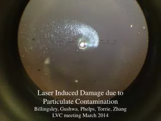
Besides spectroscopy and Langmuir probes, witness plates served as our primary diagnostic Witness plate preparation technique: • Start with single crystal Si • HF acid dip to strip native oxide • Spin, rinse, dry • Controlled thermal oxide growth at 1350 K to ~1mm, 4 Å roughness • Ta/Au sputter coat for SEM • Locate witness plate near plume stagnation point Witness plate prior to exposure, showing a single defect in the native crystal structure
Measurement of final condensate size 500 mTorr He 5x10⁸ W/cm2 5x10⁹ W/cm2 5x10⁷ W/cm2 • Good correlation between laser intensity and cluster size is observed. • Is it due to increasing saturation ratio or charge state? 5x10⁸ W/cm2 5x10⁹ W/cm2
Saturation ratio and charge state derived from experimental measurements • Saturation ratio is inversely related to laser intensity! Saturation ratio derived from spectroscopy, assuming LTE Maximum ionization state derived from spectroscopy, assuming LTE
Cluster size distribution – comparison of theory & experiment The discrepancy at low irradiance is believed to be caused by anomolously high charge state induced by free electrons
Summary and future work • We have obtained a better understanding of the mechanisms which form particulate in laser plasma • Clusters in the size range from 5-50 nm are routinely produced at moderate laser intensity • Model predictions appear to match experimental data • In-situ particle measurements (scattering, spectroscopy) would be very useful to further validate the mechanisms • Better control of size distribution and enhanced yield are desired • Model improvements are needed: 2-D, kinetic treatment • Applications of nanoclusters & quantum dots will be explored research supported by the US Department of Energy, Office of Fusion Energy Sciences and the Hewlett Packard Company, Printing and Imaging Group