Download
1 / 17
220 likes | 671 Views
Chapter Seven Micro programmed Control Organization. Control word. External Input. Next address Generator (Sequencer). Control address register. Control memory (Rom). Control data register. Next-address information. Figure 7– 1 Micro programmed Control Organization.

E N D
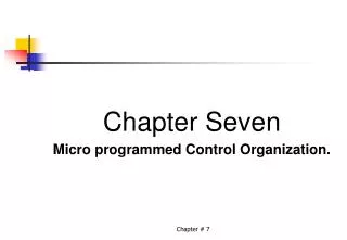
Chapter Seven Micro programmed Control Organization. Chapter # 7
Control word External Input Next address Generator (Sequencer) Control address register Control memory (Rom) Control data register Next-address information Figure 7– 1Micro programmed Control Organization. Chapter # 7
Instruction code Mapping logic Status bits Branch Logic MUX Multiplexers Select Subroutine registers (SBR) Control address register Incrementer Control memory Select a status bit Branch address Micro operations Figure 7– 2Selection of Address for control memory. Chapter # 7
Opcode 1 0 1 1 Address Computer instruction Mapping bits 0 0 0 x x x x 0 1 0 1 1 0 0 Microinstruction address Figure 7– 3Mapping from instruction code to micro instruction address. Chapter # 7
MUX 0 10 Memory 2048 x 16 AR Address 0 10 PC MUX 6 0 6 0 0 15 SBR CAR DR Control memory 128 x 20 Arithmetic logic and shift unit 0 15 Control unit AC Figure 7– 4Computer hardware configuration. Chapter # 7
Figure 7– 5Computer instructions. 15 14 11 10 0 (a) Instruction format Description Symbol Code ADD 0000 Ac Ac + M [EA] BRANCH 0001 if (AC < 0) then (PC EA) STORE 0010 M [EA] AC EXCHANGE 0011 AC M [EA], M [EA] AC EA is the effective address (b) Four computer instructions Chapter # 7
Figure 7– 5Micro instructions code format. 3 3 3 2 2 7 F1, F2, F3:Micro operation fields CD:Condition for branching BR:Branch field AD:Address field Chapter # 7
F1 Micro operation Symbol 000 None NOP 001 AC AC + DR ADD 010 AC 0 CLRAC 011 AC AC + 1 INCAC 100 AC DR DRTAC 101 AR DR (0-10) DRTAR 110 AR PC PCTAR 111 M [AR] DR WRITE F2 Micro operation Symbol 000 None NOP 001 AC AC – DR SUB 010 AC AC DR OR 011 AC AC ^ DR AND 100 DR M [AR] READ 101 DR AC ACTDR 110 DR DR + 1 INCDR Table 7-1Symbol and Binary Code for Micro instructions Continued Chapter # 7
F3 Micro operation Symbol 000 None NOP 001 AC AC DR XOR 010 AC AC COM 011 AC shl AC SHL 100 AC shl AC SHR 101 PC PC + 1 INCPC 110 PC AR ARTPC 111 Reserved CD Condition Symbol Comments Table 7-1Symbol and Binary Code for Micro instructions 00 Always = 1 U Unconditional branch 01 DR (15) I Indirect address bit 10 AC (15) S Sign bit of AC 11 AC = 0 Z Zero value in AC Continued Chapter # 7
BR Symbol Function 00 JMP CAR AD if condition = 1 CAR CAR + 1 if condition = 0 01 CALL CAR AD, SBR CAR + 1 if condition = 1 CAR CAR + 1 if condition = 0 10 RET CAR SBR (Return from subroutine) 11 MAP CAR (2-5) DR (11-14), CAR (1, 1, 6) 0 Table 7-1Symbol and Binary Code for Micro instructions Chapter # 7
AR PC DR M [AR], PC PC + 1 AR DR (0-10), CAR (2-5) DR (11-14), CAR (0, 1, 6) 0 Assembly language convention of fetch ORG 64 PCTAR U JMP NEXT READ,INCPC U JMP NEXT DRTAR U MAP FETCH: Bit representation of the program Binary Address F1 F2 F3 CD BR AD 1000000 110 000 000 00 00 1000001 1000001 000 100 101 00 00 1000010 1000010 101 000 000 00 11 0000000 Fetch Routine Chapter # 7
Label Micro operations CD BR AD ORG 0 ADD: NOP I CALL INDRCT READ U JMP NEXT ADD U JMP FETCH ORG 4 BRANCH: NOP S JMP OVER NOP U JMP FETCH OVER: NOP I CALL INDRCT ARTPC U JMP FETCH ORG 8 STORE: NOP I CALL INDRCT ACTDR U JMP NEXT WRITE U JMP FETCH ORG 12 EXCHANGE: NOP I CALL INDRCT READ U JMP NEXT ACTDR, DRTAC U JMP NEXT WRITE U JMP FETCH Table 7-2Symbol Micro program. Chapter # 7 Continued
Label Micro operations CD BR AD ORG 64 FETCH: PCTAR U JMP NEXT READ, INCPC U UMP NEXT DRTAR U MAP INDRCT: READ U JMP NEXT DRTAR U RET Table 7-2Symbol Micro program. Chapter # 7
Address Binary Micro instructions µ.Routine Decimal Binary F1 F2 F3 CD BR AD ADD 0 0000000 000 000 000 01 01 1000011 1 0000001 000 100 000 00 00 0000010 2 0000010 001 000 000 00 00 1000000 3 0000011 000 000 000 00 00 1000000 BRANCH 4 0000100 000 000 000 10 00 0000110 5 0000101 000 000 000 00 00 1000000 6 0000110 000 000 000 01 01 1000011 7 0000111 000 000 110 00 00 1000000 STORE 8 0001000 000 000 000 01 01 1000011 9 0001001 000 101 000 00 00 0001010 10 0001010 111 000 000 00 00 1000000 11 0001011 000 000 000 00 00 1000000 EXCHANGE 12 0001100 000 000 000 01 01 1000011 13 0001101 001 000 000 00 00 0001110 14 0001110 100 101 000 00 00 0001111 15 0001111 111 000 000 00 00 1000000 FETCH 64 1000000 110 000 000 00 00 1000001 65 1000001 000 100 101 00 00 1000010 66 1000010 101 000 000 00 11 0000000 INDRCT 67 1000011 000 100 000 00 00 1000100 68 1000100 101 000 000 00 10 0000000 Table 7-3Binary Micro program for control memory. Chapter # 7
F1 F2 F3 3 x 8 decoder 3 x 8 decoder 3 x 8 decoder 7 6 5 4 3 2 1 0 7 6 5 4 3 2 1 0 7 6 5 4 3 2 1 0 AND Arithmetic logic shift unit ADD DRTAC From PC From DR (0-10) PCTAR DRTAR LOAD AC Multiplexers 0 1 Select 11 LOAD AR CLOCK Figure 7-7Decoding of Micro instruction field. Chapter # 7
External (Map) MUX 1 3 2 1 0 Input Logic I0 LOAD S1 I1 So SBR T Test Incrementer MUX 2 Select I CAR I S Z Control Memory CD BR AD Microops Figure 7-8Micro program sequencer for control memory. Chapter # 7
BR Input MUX 1 Load SBR Field I 1 I 0 T S 1S O L Table 7-4Input Logic Truth table for Micro program Sequencer 0 0 0 0 0 0 0 0 0 0 0 0 1 0 1 0 0 1 0 1 0 0 0 0 0 1 0 1 1 0 1 1 1 0 1 0 x 1 0 0 11 1 1 x 1 1 0 Chapter # 7