Download
1 / 48
730 likes | 1.61k Views
Specific Energy . Channel transitions Steps, cross-section Slope change Local loss locations Gate Piers Hydraulic Jump. EGL. v 2 /2g. y. y c. D z. datum. 1. 2. If we assume no energy loss through the transition we can say:.

E N D
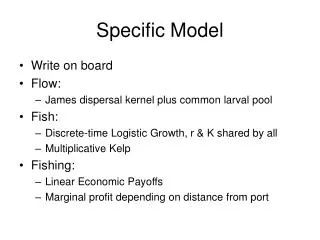
Specific Energy • Channel transitions • Steps, cross-section • Slope change • Local loss locations • Gate • Piers • Hydraulic Jump CJM
EGL v2/2g y yc Dz datum 1 2 • If we assume no energy loss through the transition we can say: which says for a constant total energy E, there is a specific energy loss between 1-2 of Dz. CJM
Open Channel Hydraulics • Three basic relationships • Continuity equation • Energy equation • Momentum equation CJM
3a Inflow 3 A Change in Storage 3b Outflow 1 2 A Section AA Continuity Equation Inflow – Outflow = Change in Storage CJM
Area of the cross-section (ft2) or (m2) Avg. velocity of flow at a cross-section (ft/s) or (m/s) Flow rate (cfs) or (m3/s) General Flow Equation Q = vA CJM
3 A 3 Section AA 1 2 A Q1 Q2 Q1 – Q2 = Change in storage rate CJM
elevation head velocity head Energy loss between sections 1 and 2 pressure head Energy Equation (Bernoulli’s) CJM
Open Channel Energy Equation • In open channel flow (as opposed to pipe flow) the free water surface is exposed to the atmosphere so that p/g is 0 (on the surface; or p/g is y at the invert), leaving: CJM
Q Channel Bottom z1 z2 Datum 2 1 CJM
HGL y1 y2 Channel Bottom z1 z2 Datum 1 2 CJM
EGL HGL y1 y2 Channel Bottom z1 z2 Datum 2 1 CJM
hL1-2 EGL HGL y1 y2 Channel Bottom z1 z2 Datum 1 2 CJM
A E y Datum and channel bottom A Eqn. 2.2 Specific Energy E is the specific energy. CJM
y Section AA q = vy Where q is the flow per unit width. (Eqn. 2.4) Specific Energy (cont.) Eqn. 2.2 becomes: CJM
y y=E y2 yc y1 Ec E Eo Specific Energy Diagrams *Note q is constant. CJM
or Critical Depth, yc • The depth of flow corresponding to the minimum E is the critical depth, yc CJM
Channel transitions occur where there is a change in width, shape, slope, roughness, bottom elevation of the channel. • For changes in slope and roughness we can use backwater curves to evaluate the effects of the changes. • For other types of smooth transitions (transitions were energy loss is minimal), we can use energy relationships to evaluate the impact of the transition. CJM
EGL v2/2g y yc Dz datum 1 2 • If we assume no energy loss through the transition we can say: which says for a constant total energy E, there is a specific energy loss between 1-2 of Dz. CJM
y y=E y1 y2 Dz yc E2 E1 E Specific Energy Representation of a Transition CJM
If the flow must pass through critical depth, the assumption of no energy loss may not be valid. • This is especially true when going from supercritical to subcritical flow. • A hydraulic jump accompanied by considerable energy loss occurs. CJM
Other Minimum Specific Energy Relations • Froude Number: Minimum Specific Energy • Emin:yc • Wave speed of small disturbance CJM
DERIVATIONS • E = y + v2/2g • E = y + q2/2gy2 • dE/dy = 0 = 1- q2/gyc3 • yc = (q2/g) 0.333……(eqtn 2.6)……..SO…..!!!!!…… • Emin = yc + q2/2gyc2 = 3/2 yc • Emin = 3/2 yc CJM
is known as the Froude Number, F Froude Number, F • Compare to (2.6) : q2/gyc3 = 1 • Then, vc2/gyc = 1 at critical conditions • So, at critical conditions, the Froude number =1! CJM
……..Tie in with wave speed • Speed of a small disturbance on water can be shown to be: vw = (gy)1/2 • So, at critical conditions…surface wave has same velocity as the river (vw = vc) CJM
Flow classification based on Froude number • If F = 1, y = yc and flow is critical. • If F < 1, y > yc and flow is subcritical. • If F > 1, y < yc and flow is supercritical. • F is independent of the slope of the channel, yc dependent only on Q. CJM
Critical Step Height • Figure 2.6: Approach Froude number vs non-dimensional step height (Dz/y1) CJM
Example 2.1 For an approach flow in a rectangular channel with depth of 2.0 m (6.6 ft) and velocity of 2.2 m/s (7.2 ft/s), determine the depth of flow over a gradual rise in the channel bottom of Dz = 0.25 m (0.82 ft). Repeat the solution for Dz = 0.50 m (1.64 ft). CJM
EGL v2/2g V1 = 2.2 Y1= 2.0 y2 Dz = 0.25 datum 1 2 • If we assume no energy loss through the transition we can say: which says for a constant total energy (TE), there is a specific energy loss between 1-2 of Dz (meters). CJM
Steps • Determine U/S Condition (sub- or super-) • Calculate critical depth, compare to u/s depth • Alternately, calculate F1 • Solve specific energy equation for correct root for y2, v2 • Water surface elevation = y2 + Dz CJM
Repeat for a step of 0.50 m • Check value of Emin • Determine value of E2 = (E1-Dz) • Find E2<Emin (CAN’T BE!!!!) • Flow “backs-up” to allow passage of q • Y1 increases; conditions at step are critical, with y2 = yc; E2 = Emin CJM
Contraction/Expansion in Width width1 width2 Plan View 1 2 • If we assume no energy loss through the transition we can say: V12/2g + y1 = V22/2g + y2 OR q12/2gy12 + y1 = E1 = E2 = q22/2gy22 + y2 q2 and q1 related by continuity .. So two equations; two unknowns CJM
Continuity • q1w1 = q2w2 = Q • q2 = q1 w1/w2 Now, find y2 (3 roots, 2 real…find one that matches with upstream flow condition) Ensure that flow isn’t “choked” by contraction condition CJM
q1 y q2>q1 y1 y2 E CJM
Choking Condition q1 y q2 y1 E E1< E2min CJM
Revised Upstream Condition q1 y q2 y1 y1 THIS IS THE CONTROL! y2 E E1 = E2 = Emin (q2) CJM
yc, General Form • E = y + Q2/2gA2 • Differentiate with respect to y and set DE/dy = 0; find minimum point; ie condition where E = Emin; y = yc • dE/dy = 0 =1 – Q2/gA3 (dA/dy) • 1 = Q2/gA3 (dA/dy) • (if you can determine dA/dy, and can write A(y), can find yc) CJM
General Channel Shape B(y) dy dA=Bdy y A(y) CJM
dA/dy = B (topwidth, B(y)) • So, Q2Bc/gAc3 = 1 (2.18) • Define hydraulic depth D = A/B • V = Q/A • F = V/(gD)1/2 or V/(gD/a)1/2 • Minimum specific energy, Emin = yc + Dc/2 • (From 2.16 and 2.18) CJM
Solve for yc in a non-rectangular channel: • aQ2Bc/gAc3 = 1 • Find value of yc that satisfies this equality • Geometric Elements in Table 2-1 CJM
Example 2.2 • Find the critical depth in a trapezoidal channel with a 20 ft bottom width and 2:1 side slopes if Q = 1000 cfs. Use the bisection technique and compare the solution with that from Figure 2.13 1 2 20’ CJM
F(y) = Q – (g1/2A3/2)/B1/2 • YOYC provides solution OR • Graphical technique (Figure 2.13) • yc = 3.740 feet CJM
Overbank Flow Flood Stage Normal Stage CJM
Overbank Flow: calculate yc • Can’t neglect a • Must consider variation of a withy • dE/dy = 1 – aQ2B/gA3 + Q2/2gA2 da/dy • (2.16 differentiated with A(y) and a(y)) CJM
Overbank Flow (Compound Channel) continued • Fc=(aQ2B/gA3 – Q2/2gA2 da/dy)0.5 • Use Ycomp! CJM