Download

1 / 103

E N D
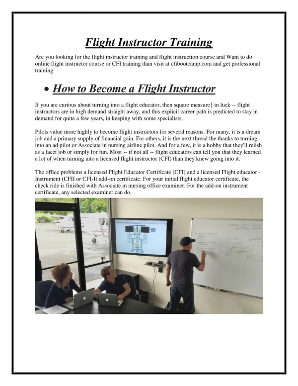
1. SARASOTA FLIGHT INSTRUCTOR.COM
4. Disclaimers This guide is based on the Pilot Operating Handbook for the Piper Seneca model PA34-200T.
This guide is for study purposes only, and in no way should be considered a single source of information regarding any flight, system, or emergency operation.
Images used herein are either original images, or obtained from open source files.
Use this program along with the actual Pilots Operating Handbook, your Instructor and your training curriculum.
5. Section 1 General
6. Engines
7. Engines Number of engines
2
Engine Type:
Six Cylinder
Direct Drive
Horizontally Opposed
Fuel Injected
Air Cooled
Turbo charged
Engine Manufacturer
Continental
Engine Model Numbers:
Left TSIO-360E (EB)
Right LTSIO-360E (EB)
8. ENGINES Rated Horsepower:
At sea level 200
Above 12,000 feet 215
Rated Speed (rpm)
2575
Bore (inches)
4.438
Stroke (inches)
3.875
Displacement (cubic Inches)
360
Compression Ratio
7.5:1
9. PROPELLERS Number of Propellers
2
Propeller Manufacturer
Hartzell or McCauley
Propeller Type:
Constant Speed
Hydraulically Actuated
Full Feathering
Blades:
Hartzell 2
McCauley 3
10. FUEL Fuel Capacity (U.S. Gal)
Without optional tanks 98
With optional tanks 128
Useable Fuel (U.S. Gal)
Without optional tanks 93
With optional tanks 123
Minimum Fuel Grade:
100 green or 100LL Blue
11. Oil Oil Capacity (U.S. quarts)
8
Oil Specification
Per Continental Service Bulletin
Oil Viscosity per ambient temp:
Below 40� F SAE No. 30
Above 40� F SAE No. 50
Minimum for flight is 7 quarts
12. Maximum Weights Max Takeoff Weight:
4570 lbs.
Max Landing Weight
4342 lbs.
Max Zero Fuel Weight
4000 lbs.
Maximum Weights in Baggage Compartments:
Forward 100
Aft 100
13. Standard Airplane Weights Standard Empty Weight
2823
Maximum Useful Load
1747
14. Baggage Space Forward compartment volume
15.3 cubic feet
Aft compartment volume
24.0 cubic feet
15. Specific Loadings Wing Loading
22 lbs sq ft
Power Loading Sea Level
11.4 lbs sq ft
Power Loading 12,000 ft
10.6 lbs sq ft
16. Section 2 Limitations
17. Airspeed Limitations Vne Never Exceed
195
Vno Max structural cruise
163
Va Maneuvering speed
At 4570 lbs
136
At 3068 lbs
121
Vfe Flaps extended
107
Vmc Minimum Control Speed
66
18. Airspeed Limitations Vfe Flaps extended
107
Vle Maximum gear extended
129
Vlo Maximum gear �extending�
129
Vlo Maximum gear �retraction�
107
19. Airspeed Indicator Markings
Green Arc (normal Operating range)
63 to 163
Yellow Arc (caution range � smooth air)
163 to 195
White Arc (flaps extended)
61 to 107
Red Radial Line (never exceed)
195
Red Radial Line (minimum control)
66
Blue Radial Line (best rate climb single engine)
89
20. Power Plant Limitations Rated Horsepower at sea level
200
Rated Horsepower at 12,000 ft
215
Maximum RPM
2575
Maximum Manifold Pressure (inches)
40
Maximum Cylinder Head Temp.
460�
Maximum Oil Temp.
240�
21. Power Plant Limitations Maximum oil pressure
100 PSI
Minimum oil pressure
10 PSI
Minimum fuel flow
3.5 PSI
Maximum fuel flow
20 PSI to 25 GPH
22. Power Plant Instrument Markings Tachometer - Green Arc (normal range)
500 rpm to 2575 rpm
Tachometer - Red Line (maximum)
2575 rpm
Fuel Flow and Pressure:
Green Arc
3.5 PSI to 20 PSI
Red Line (max)
25 GPH (20 PSI)
Red Line (min)
3.5 PSI
23. Power Plant Instrument Markings Cylinder Head Temperatures
Maximum (red line)
460 �
Normal Range (green arc)
360 � to 460 �
Oil Temperature
Maximum
240 �
Normal Range (green arc)
100 � to 240 �
Oil Pressure
Maximum
100 PSI
Minimum
10 PSI
Caution
80 to 100 PSI
24. Power Plant Instrument Markings Manifold Pressure
Normal Range (green arc)
10 to 40 inches HG
Maximum (red line)
40 inches HG
Exhaust Gas Temperature
Red Line 1650� F
25. Weight Limits Maximum Takeoff Weight
4570
Maximum Landing Weight
4342
Maximum Weight in Forward Baggage
100
Maximum Weight in Aft Baggage
100
Maximum Zero Fuel Weight
4000
26. Center of Gravity Limits Weight Forward Limit Aft Limit
Pounds Inches Aft of Datum Inches Aft of Datum
3400 82.0 94.6
4575 90.6 95.6
Note: Datum is 78.4 inches forward of the leading edge from the inboard edge of the fuel tank.
27. Maneuver Limits All intentional Acrobatic Maneuvers are prohibited
28. Flight Load Factor Limits [Flaps UP]
Positive Load Factor (Max.)
3.8 G
Negative Load Factor (Max.)
0.0 G
No inverted maneuvers approves.
29. Types of Operations This plane is equipped in accordance with FAR91 or FAR135 for the following operations:
Day VFR
Night VFR
Day IFR
Night IFR
Icing Conditions when equipped per section 2.25 of the pilot operations manual.
30. Fuel Limitations Un-useable Fuel U.S. Gallons
2.5 gal each wing
Total of 5.0 gallons
Useable Fuel U.S. Gallons
46.5 each wing Total of 93 (standard tanks)
61.5 each wing Total of 123 (optional tanks)
31. Gyro Pressure Limitations
Operating Limits for the vacuum pressure:
4.5 to 5.2 inches Hg for all operations.
32. Flight into known icing conditions The following must be installed
Pneumatic Wing and Empennage Boots
Electro-thermal Propeller Boots
Electric Windshield Panel
Heated Pitot Head
Wing Ice Light
Heated Lift Detectors
Propeller Spinners must be installed.
33. Heater Limitations Operation of the combustion heater above 25,000 feet is not approved.
34. Operating Altitude Limitations Flight above 25,000 feet is not approved.
Flight up to 25,000 if equipped with supplemental oxygen.
35. Noise Levels The noise level on this aircraft is as follows
With 2 blade Propellers
73.5 dB(A)
With 3 blade Propellers
76.4 dB(A)
36. Section 3 Emergency Procedures
37. Emergency Checklists Use the checklist provided by the manufacturer.
38. Airspeeds for Safe Operation Minimum Single Engine Control
66 KIAS
Best Single Engine Rate Climb
89 KIAS
Best Single Engine Angle Climb
78 KIAS
Maneuvering
121 KIAS
Never Exceed
195 KIAS
39. Engine Inoperative Procedures DETECTING DEAD ENGINE
Loss of thrust
Nose will Yaw towards inoperative engine
40. Engine Failure on Takeoff Below 85 KIAS- On-Runway
Throttles
Close Both Immediately, Maintain Directional Control
Brake and Stop
Airborne with no runway remaining
Throttles
Close Both Immediately, Maintain Directional Control
Mixture
Idle Cut-Off
Fuel Selectors
Off
Land
Try to avoid obstructions
41. Engine Failure During Climb/ Speed Below 66 KIAS (Vmc) Rudder
Apply Towards Operating Engine (Control)
Throttles
Reduce Thrust to Maintain Directional Control
Pitch Attitude
Lower Nose to Accelerate to Vyse (89KIAS)
Inoperative Engine
Feather and Secure (Checklist)
42. Engine Failure During Climb/Speed Above 66 KIAS Rudder
Maintain Directional Control
Pitch Attitude
Adjust to Accelerate to Vyse (89KIAS)
Inoperative Engine
Feather and Secure (Checklist)
43. Engine Failure During Flight/Below 66 KIAS Rudder
Towards Operating Engine, Maintain Directional Control
Throttles
Retard to prevent yaw
Pitch Attitude
Lower Nose for 66 KIAS+
Operating Engine Increase power as speed permits (66 KIAS+)
If Altitude Permits
Restart may be attempted (Restart Checklist)
If No Restart, or Altitude does not permit
Inoperative Engine
Feather and Secure (Checklist)
Trim
Adj. UP TO 5� Bank toward operating engine (minimal Slip)
Cowl Flap on operating engine as required
44. Engine Failure During Flight Above 66 KIAS Rudder
Apply toward operative engine
Inop. Engine
Identify
Operating Engine
Adjust thrust as required
Before Securing Inop. Engine---
Fuel Flow - Check (if Low use Aux. Pump HIGH BOOST)
If power is not restored Aux Pump � Off
Fuel Quantity Check
Fuel Selector (Inop. Engine) Cross-Feed
Alternate Air On
Mixture Check
Oil Pressure and Temp. Check
Magneto Switches Check
If Engine Fails to Start proceed to Engine Securing Checklist
45. Engine Failure During Flight Above 66 KIAS (cont) OPERATING ENGINE
Power Setting
As required
Mixture
Adjust for Power Setting
Fuel Quantity
Check for sufficient supply
Aux. Fuel Pump
As Required
Cowl Flaps
As Required
Electrical Load
Decrease to minimum load
Land
As soon as possible
46. Engine Securing Checklist To Attempt to Restore Power before feathering
Mixtures
As Required
Fuel Selector
Cross Feed
Magnetos
Left or Right only
Alternate Air
On
Aux. Fuel Pump
Unlatch
On HIGH if power not restored
47. Engine Securing Checklist FEATHERING MAINTAIN DIRCETIONAL CONTROL
AND AT LEAST 76 KIAS
Mixture Controls
Full Forward
Propeller Controls
Full Forward
Throttle Controls
Full Forward (40�Hg Max)
Flaps
Retract
Gear
Retract
48. Engine Securing Checklist FEATHERING
49. Single Engine Landing Inoperative Engine
Feather and Secure
When Landing Assured
Landing Gear Extend
Wing Flaps Extend to 10�
Maintain Additional Altitude and speed during approach
Final Approach Speed 91 KIAS
Wing Flaps
Extend to 25�
50. Single Engine Go-Around Mixture
Forward
Propeller
Forward
Throttle
Forward Slowly to 40� Hg
Flaps
Retract
Landing Gear
Retract
51. Air Start (Un-feathering) Fuel Selector INOP Engine
On
Aux. Fuel Pump INOP Engine
Off
Throttle
Open � Inch
Propeller Control
Forward to Cruise RPM Pos.
Mixture
Rich
Magneto Switches
On
52. Engine Fire On Ground ENGINE NOT STARTED
Mixture
Idle Cut-Off
Throttle
OPEN
Starter
Continue To Crank engine
53. Engine Fire In Flight Fuel Selector (affected engine)
Off
Throttle
Close
Mixture
Idle Cut-Off
Propeller
Feather
54. Fuel Management Single Engine Fuel Selector Operating Engine
On
Fuel Selector INOP Engine
Off
Aux. Fuel Pumps
Off
55. Fuel Management Single Engine
56. Fuel Management Single Engine
Fuel Selector Operating Engine
On
Fuel Selector INOP Engine
Off
57. Fuel Management Single Engine
Use Cross-Feed in Level Flight Only
Do NOT Cross-Feed with Full Fuel on same side as the Operating Engine,
Vapor Return Fuel will be lost though the Vent System
You will be pumping fuel over-board
58. Engine Driven Fuel Pump Failure Throttle
Retard
Aux. Fuel Pump
Un-Latch
Aux. Fuel Pump
On HI
Throttle
Re-set 75% Power or lower
See Cautions:
59. Engine Driven Fuel Pump FailureCautions If normal engine operation and fuel flow is not immediately re-established,
Turn OFF Aux. Fuel Pump
Lack of fuel flow indications while in the HI position may indicate a leak in the fuel system, or fuel exhaustion
Do NOT actuate the Aux. Fuel Pump unless vapor suppression is required (LO position) or the engine driven fuel pump fails (HI Position).
The Aux. Fuel Pumps have NO Standby Function.
Actuation of the HI switch position may when engines are operating may cause engine roughness and / or Power Loss.
60. Landing Gear Unsafe Warning Red Light
Gear In Transit
Recycle if Unsafe Gear Indication continues
Light will illuminate when Gear Horn sounds at Low Power Settings
61. Manual Extension of Landing Gear Check the following before extending gear manually:
Circuit Breakers
Check
Master Switch
On
Alternators
Check
Navigation Lights
Off (Daytime)
62. Engine Failure in Icing Conditions Select Alternate Air and attempt restart
In unable to restart engine
INOP Engine
Secure
Airspeed
at or above 89 KIAS
Electrical Load
Reduce
63. Alternator Failure In Icing Conditions Over-voltage Relay
Re-set
Circuit Breakers
Check and Re-set
If unable to restore alternator
Avionics
All Off except NAV/COM/Transponder
Electric Windshield
Off to maintain 65 amp load
64. Electrical Failures ALT Anunnciator Light illuminated
Ammeters Observe to determine INOP Alt.
If both ammeters show zero output, reduce electrical load to min.
Turn Off both alt. switches; then turn them On momentarily one at a time while observing ammeters
Determine Alt. showing Least output and turn it�s switch on.
Electrical Loads Re-establish up to 60 Amps
If one ammeter shows zero output, cycle switch off-then-on
If power is not restored, check breakers and reset once if required
If alternator remains inoperative, reduce electrical loads and continue flight
65. Electrical Failure Cautions Compass error may exceed 10� with both alternators Inoperative.
66. Gyro Pressure Failures Pressure Below 4.5 inches Hg
(Hint�.. DON�T TAKEOFF IFR)
RPM
Increase to 2575
Altitude
Descend to maintain 4.5 inches Hg
Use Electric Turn Indicator to monitor Directional Gyro and Attitude Indicator performance
67. Combustion Heater Over-heat Unit will automatically cut-off
Do not Attempt to re-start.
68. Spins Throttles
Idle
Rudder
Opposite direction of spin
Control Yoke
Release Back Pressure
Control Yoke
Full forward if nose does not drop
Ailerons
Neutral
69. Emergency Descent Throttles
Closed
Propellers
Full Forward
Mixture
As Required
Landing Gear
Extend
Airspeed
129 KIAS
70. Section 3 Normal Procedures
71. Before Starting Engines Seats
Adjusted
Seat Belts
On
Parking Brake
On
Circuit Breakers
In
Radios
OFF
72. Starting Engines Fuel Selector
On
Mixture
Rich
Throttle
� Open
Propeller
Forward
Master Switch
On
Ignition Switches
On
Propeller
Clear
73. Starting Engines when Flooded Mixture
Idle Cut-Off
Throttle
Full Forward
Propeller
Forward
Master Switch
On
Ignition Switch
On
74. Starting Engines-External Power Master Switch
Off
All Electrical Equipment
Off
Terminals
Connect
External Power Plug
Insert into receptacle
Proceed with Normal Start Procedures
75. Warm Up Throttles
1,000 to 1,200 RPM
76. Taxiing Chocks
Remove
Taxi Area
Clear
Throttle
Apply Slowly
Brakes
Check
77. Before Takeoff � Ground Check (part 1) Parking brake
Set
Mixture Controls
Forward
Propeller Controls
Forward
Throttle Controls
1000 RPM
Manifold Pressure Lines
Drain
Propeller Controls
Check Feathering
300 RPM Max. Drop
78. Before Takeoff � Ground Check (part 2) Alternator Output
Check
Gyro Pressure
4.5 to 5.2 inches Hg
Throttles
800 to 1000 RPM
Fuel Selectors
On
Alternators
On
Engine Gauges
In the Green
79. Before Takeoff � Ground Check (part 3) Quadrant friction
Set
Alternate Air
Off
Seatbacks
Erect
Wing Flaps
Set
Trim
Set
80. Takeoff Cautions Do not exceed 40 inches Manifold Pressure.
Fast Taxi turns immediately prior to takeoff run can cause temporary malfunction of one engine during takeoff.
Normal sea level takeoff at 39� Hg and 2575 RPM.
Adjust mixture prior to takeoff for High Elevation Airports.
DO NOT EXCEED 40� Hg Manifold Pressure
81. Normal Takeoff (Flaps Up) On Runway
Strobes
On
Transponder
On
Landing Light
On
Flaps
Up
Stabilator Trim
Takeoff Range
82. Short Field Takeoff (Flaps Up) On Runway
Strobes
On
Transponder
On
Landing Light
On
Flaps
Up
Stabilator Trim
Takeoff Range
83. Short Field Takeoff (Flaps 25�) On Runway
Strobes
On
Transponder
On
Strobes
On
Landing Light
On
Flaps
25�
Stabilator Trim
Takeoff Range
84. Takeoff Climb Mixture
Full Rich
Propeller Speed
2575 RPM
Manifold Pressure
40 inches Hg Max.
85. Cruise Climb Mixture
Full Rich
Prop Speed
2450 RPM
Manifold Pressure
31.5 inches Hg
Climb Speed
102 KIAS
Cowl Flaps
As required
86. Cruising Power
Set
Cowl Flaps
As Required
Mixture
Adjust
Engine Gauges
Monitor
87. Descent Mixtures
Enrich with descent
Throttles
Cruise Setting
Cowl Flaps
CLOSED
88. Approach and Landing (part 1) Gear Warning Horn
Check
Airspeed
98 KIAS downwind
Seat backs
Erect
Seat Belts
On
Fuel Selectors
On
89. Approach and Landing (part 2) Base Leg
97 KIAS
Final
87 KIAS
Close Final
Power
Reduce
Propeller Controls
Full Forward
90. Go Around Full Takeoff Power
40� Hg Max.
Flaps
Retract
Gear
Up
Cowl Flaps
Adjust
91. After Landing Clear of Runway
Transponder
Off
Strobes
Off
Landing Light
Off
Radios
Set
Flaps
Up
Cowl Flaps
Full Open
Alternate Air
Off
92. Shutdown Heater
Fan 2 min. then off
Radio and Electrical Equipment
Off
Mixture Controls
Idle-Cut-Off
93. Section 7 SYSTEMS
Description and Operation
94. The Airplane
Airframe is constructed with Aluminum Alloy
Exceptions are landing-gear struts, cowling bowls, nose-cone, and ABS plastic components on the tail, wingtips, rudder and stabilator
Fuselage is semi-monocoque in design
Front-door on the right and a rear door on the left, with a cargo door installed aft of the rear door
A door on the nose section provides access to the forward baggage storage
95. The Airplane
Wing is conventional design
Laminar flow NACA 65 2 � 415
The 4-position wing flaps are mechanically operated by a handle located between the front seats
Each wing contains 2 fuel tanks (optional 3rd) and are filled by a single filler neck located outboard of each engine nacelle
96. The Airplane
The Empennage is made up of the following: A vertical Stabilizer, an all-moveable horizontal stabilator, and a rudder
The stabilator incorporates an anit-servo trim-tab which improves longitudinal stability, and provides longitudinal trim
This tab moves in the same direction as the stabilator, but with increased travel
Rudder effectiveness is increased by an anti-servo tab on the rudder
97. The Engines
The Seneca II is powered by 2 Teledyne Continental Six-cylinder turbo-charged engines rated at 200 hp at 2750 RPM at sea level
The engines are air-cooled, fuel injected, and are equipped with oil coolers, a low temperature bypass system, and engine mounted oil filters
Asymmetric Thrust during takeoff is and climb is eliminated by counter-rotation of the engines with the left rotating clockwise, and the right rotating counter-clockwise
98. The Engines Ray-Jay turbo-chargers on each engine are powered by exhaust gases.
Exhaust gases rotate a turbine wheel, which in turn drives an air compressor
Induction Air is compressed and distributed into the engine air manifold, and the exhaust gases which drive the compressor are discharged overboard
Engine induction air is taken from within the cowling, filtered, then directed to the compressor inlet
Each cylinder is supplied with pressurized air in operations to maximum altitude
A pressure relief valve protects the engines from exceeding 42�Hg
Turbo by-pass orifice is set for 40� Hg at 12,000 Dens. Alt at full pwr
99. The Engines Intake air-box incorporates a manually operated 2way valve designed to allow induction air to either pass into the compressor through the filter or to bypass the filter and supply heated air directly to the turbocharger
There is a suck-in-door which opens in the event the primary air source becomes blocked
Alternate-Air selection assures induction air flow should the primary air source become blocked
This air is heated an thus protects against blockage due to snow or freezing rain
Alternate is un-filtered and should not be used during ground operations
Primary air should always be used during takeoff
100. The Engines The Fuel injection system is a �continuous flow� type
The system incorporates metering which measures the rate at which turbo-charged air is being used by the engine and dispenses fuel to the cylinders proportionally
Fuel is supplied to the injector pump at a greater rate than the engine requires
101. The Engines Engine Controls consist of individual Throttles, Propeller Controls, and Mixture controls for each engine
Engine controls are located on the control quadrant on the lower center of the instrument panel
The controls use teflon-lined control cables to reduce friction and binding
Throttles are used to control manifold pressure an incorporate a gear-up warning switch that is activated when the throttles are closed and the landing gear is not down
102. The Engines The Propeller Control levers are used to adjust the propeller speed form high RPM to Feather
The Mixture Control levers are used to adjust the air-to-fuel ratio
An engine is shut-down by placing the mixture control in the full lean (idle-cut-off) position
Alternate air controls are located on the control quadrant just below the engine control levers
Alternate air OFF (up) provides normal filtered air
Alternate air ON (down) provides unfiltered, heated air
103. The Engines Cowl flap controls are located just below the control quadrant and have three positions� full open, full closed, and intermediate
The cowl flap controls lock in each selected position
The lock must be depressed to move to another position
ALL THROTTLE OPERATIONS SHOULD BE MADE WITH SMOOTH NOT-TO-RAPID MOVEMENTS TO PREVENT UNECESSARY WEAR OR DAMAGE TO THE ENGINE, AND TO ALLOW TIME FOR THE TURBO-CHARGER SPEED TO STABILIZE
104. The Propellers Counter-rotating propellers provide balance thrust during takeoff and climb and eliminate the �critical engine� factor in single-engine flight
Two-blade, constant-speed, controllable pitch, feathering Hartzell propellers are standard equipment
Pitch is controlled by oil and nitrogen pressure
Oil pressure sends the a propeller toward the high RPM/un-feathered position,
Nitrogen sends the propeller toward the Low RPM/Feather position, and prevents over-speeding
Governors on each engine supply engine oil at various pressures through the propeller shafts to maintain constant RPM settings
105. The Propellers Feathering of a propeller is done by moving the control lever to the Completely through Low-RPM, Feather position
Feathering takes place in approximately six seconds
Un-feathering is accomplished by moving the propeller control lever forward and engaging the starter until the propeller is wind-milling
A feathering lock (operated by centrifugal force) prevents feathering during engine shut-down by making it impossible to feather if engine speed drops below 800 RPM
For this reason, when feathering is desired or necessary, it must be done before the engine falls below 800 RPM
106. Landing Gear The Seneca II is equipped with hydraulically operated, fully retractable, tricycle landing gear
Hydraulic pressure for gear operation is furnished by an electrically powered, reversible hydraulic pump
The Pump is activated by a two-position gear selector switch located to the left of the control quadrant on the instrument panel
CAUTION
If the landing gear is in transit and the hydraulic pump is running it is NOT advisable to move the gear selector switch to the opposite position before the gear has reached its full travel limit, because sudden reversal may damage the electric pump
107. Landing Gear The landing gear is designed to extend without the hydraulic pump
The gear is held �up� by hydraulic pressure
If the hydraulic system fails for any reason, gravity will allow the gear to extend
On retraction, the mains retract inboard into the wings, and the nose-wheel retracts forward into the nose
Aerodynamic loads and springs assist in gear extension and in locking the gear in the down position
108. Landing Gear Landing Gear Hydraulics
109. Landing Gear To extend the landing gear in the event of hydraulic failure it is only necessary to only relieve the hydraulic pressure.
Emergency gear extension must not be attempted at airspeeds in excess of 84 knots
An emergency gear extension knob is located directly beneath the landing gear extension handle for this purpose
Pulling this knob releases hydraulic pressure and allows the landing
The knob is guarded by a spring retainer that must be disengaged before pulling the knob
110. Landing Gear Landing Gear Selector and Emergency Release
111. Landing Gear When the gear is fully extended or retracted, and the gear selector is in the corresponding position, electrical limit switches stop the flow of current to the hydraulic pump
Lights directly above the Landing gear selector illuminate to indicate that all three landing gear are down and locked
If the gear is neither fully up or fully down a red warning light on the instrument panel illuminates
Should the throttles be placed in a low setting (landing) while the gear is in retracted, a warning horn sounds to alert the pilot that the gear is retracted.
The horn emits a 90 cycles per minute beeping sound
112. Landing Gear If one or two of the three green lights do not illuminate when the gear-down position is selected, any of the following conditions may exist:
-Gear not locked down
-Bulb is burned out
-There is a malfunction in the indicating system
A micro switch incorporated in the throttle quadrant activates the gear warning horn under the following conditions:
Gear not locked down and manifold pressure less than 14� Hg
The gear selector switch is in the UP position when the airplane is on the ground
113. Landing Gear To prevent accidental gear retraction should the gear selector be placed in the UP position while on the ground a SQUAT switch located on the left main landing gear will prevent the hydraulic pump from actuating if the master switch is turned on.
On takeoff, the main oleo strut drops to full extension, and the safety switch closes to complete the circuit to allow pump operation
During pre-flight be sure the landing gear selector is in the DOWN position and that 3 green lights are illuminated
On takeoff the gear should be retracted BEFORE reaching 107 KTS
The Landing gear may be extended at any speed below 129 KTS
114. Brake System The brake system is designed to meet all normal braking needs
2 single-disc, double-puck brake assemblies mounted on each main gear are actuated by toe-brake pedals mounted on both pilots rudder pedals, or by the hand operated brake level located below and behind the left center of the instrument panel
The parking brake is engaged by pulling the brake handle and depressing the button on the left of the handle
The brake is released by pulling on the brake handle and releasing
115. Flight Control System Dual flight controls are installed in the Seneca II as a standard
The controls actuate the flight control surfaces through a cable system
The stabilator is an all-moveable slab type, with an anti-servo trim tab mounted on the trailing edge. This Tab is actuated by a control wheel mounted between the seats
Ailerons are �Frise� type and allows the leading edge of the airleron to extent into the air-stream to provide increased drag and improved roll control
The vertical tail surface is fitted with a rudder which incorporates a rudder-trim tab. The rudder-trim control is located on the control console between the front seats
116. Flight Control System Flaps are manually operated and spring loaded to return to the retracted position
A four-position flap control lever between the front seats adjusts the flaps for reduced landing speeds and glide path control
The flaps have three extension settings:
10 degrees
25 degrees
40 degrees
A button on the end of the lever must be pressed before the control can be moved
117. Fuel System Fuel is stored in fuel tanks located in each wing.
The tanks in each wing are interconnected to act as a single tank.
All tanks on each wing are fueled through a port located outboard of the engine nacelle.
Fuel is consumed from the in-board tanks (refilled from outboards)
2.5 Gallons in each wing is un-useable.
Minimum fuel grade is 100 LL blue or 100 aviation grade green.
Fuel Tank Vents located under each wing are of a non-icing design.
118. Fuel System The Fuel-Injection system is a �Continuous Flow� type.
The system uses a vapor-return line leading back to the fuel tanks.
This allows vapor laden fuel to be returned to the tanks.
Each engine has an engine driven fuel pump that is a part of the fuel injection system.
119. Fuel System An Auxiliary Fuel System is provided.
The Electric powered Auxiliary fuel system supplies fuel to the engine in the event of engine-driven fuel pump shaft failure or malfunction.
The system is also used for ground and in-flight starting and for vapor suppression.
The 2 Aux. Fuel pumps switches are located on the Electrical Side panel and are 3-position rocker-switches; LO, HI. And OFF.
120. Fuel System HI Aux. Fuel Pressure is selected by pushing the Bottom of the switch. This can only be done AFTER unlatching the Guard.
When HI is selected, an Amber Light illuminates near the annunciation panel.
The lights dim whenever pump pressure reduces automatically and manifold pressure is approximately below 21� Hg.
In case of engine driven pump failure, auxiliary fuel pressure should be selected.
Adequate flow is provided for 75%
Manual leaning is required at altitudes above 15,000 ft, and for engine speeds less than 2,300 RPM.
An Hg manifold pressure switch will select lower fuel pressure when the throttle is reduced below 21� Hg, and the HI Aux fuel pump is on.
121. Fuel System NOTE:Excessive Fuel pressure and a very rich mixture will occur if the HI position is selected when the engine fuel system is operating normally.
Low auxiliary fuel pressure is available and may be used during normal engine operation on the ground and in flight for vapor suppression should it be necessary.
Indications of excessive fuel vapor are:
Unstable Engine Operations
Fluctuating Fuel Flow Indications during idle or at high altitudes.
Separate spring-loaded OFF primer button switches (adjacent to the starter switches) are used to select HI Aux fuel pump operations for priming the engines. These may be used for hot and cold engine starts.
122. Fuel System Management The controls for management of the system are located between the front seats.
There is a control lever for each engine labeled ON, OFF, X-FEED.
Normal operations the selector position is ON.
Each engine draws fuel from the wing tanks next to it.
The fuel systems for both engines are interconnected by cross-feed lines.
With X-FEED selected the engine is drawing fuel from the wing tank on the opposite side.
This allows extended range with 1 engine inoperative, and provides a balance control.
OFF shuts the fuel flow off for the engine selected.
DO NOT OPERATE with x-feed selected on both engines.
DO NOT TAKEOFF with x-feed selected.
123. Fuel System Management Before each flight, fuel must be drained low points in the system to ensure any accumulation of moisture or sediment is removed from the system.
Fuel Drains are provided for this purpose and are located�.
Each Fuel Filter (2)
Each Fuel Tank (4)
Each X-FEED Lind )2)
The Filter drains are located on the outboard underside of the nacelles.
The Tank drains are located beneath each wing.
Fuel Cross-Feed drains are located at the lowest point in the system, on the underside of the fuselage just inboard of the trailing edge of the right Flap.
124. Electrical System The electrical system is capable of supplying current for complete night IFR equipment.
Supply is provided by two 65 amp alternators (one on each engine).
A 35 ampere-hour 12 volt battery provides current for starting and for use of electrical equipment when the engines are not running.
The battery is located in the nose section and is accessible through the nose compartment baggage door.
Piper offers an optional external power plug located on the lower left side of the nose section.
An external power source or battery can be connected here without having to access the main battery.
125. Electrical System Approximately 2,000 RPM or more is required to obtain the full 65 amps.
It is NORMAL to have Zero output at idle RPM.
This is due to the reduced drive ratio of the engine.
Dual Ammeters and the ALT annunciator light provide monitoring of the electrical system.
The Ammeters indicate the output from the alternators.
Should an alternator�s ammeter indicate a much higher load than normal, that alternator should be suspected of malfunction and switched OFF.
The remaining alternator should show a NORMAL load within 1 minute.
126. Electrical System If both ammeters indicate a higher than normal load for more than 5 minutes, and electrical defect should be considered because a discharged battery will reduce the alternator load as it approaches the charged condition.
A Zero ammeter reading indicates the alternator is not producing current, and should be accompanied by illumination of the ALT light.
A Single alternator is capable of supporting continued flight with exceptions:
-With Deicing equipment and other high loads, care must be exercised to prevent loads exceeding 65 amps, and subsequently discharging the battery.
When all electrical equipment is off (except master), the ammeters will indicate current being used to charge the battery, and operate instruments.
If the sum of the two meters is significant, this indicates a low battery charge.
The pilot should try to determine why the battery charge is low, and if no cause is apparent, have the system checked.
127. Electrical System The Annunciator Panel on the upper left of the instrument panel includes lights for the following:
Manifold Pressure Overboost
Gyro Pressure
Oil Pressure
Alternator
Illumination of any light should draw the pilots attention and action should be taken to verify the validity of the warning.
Light function may be tested with a push-to-test button.
The auxiliary fuel pump lights will not illuminate with this test.
The auxiliary fuel pump lights will illuminate when the primer switches are activated.
128. Electrical System If both alternators should fail in flight, the battery becomes the primary source of electrical power.
All un-necessary equipment should be turned off.
Then time remaining on the battery is dependant on it�s charged state at the time of alternator failure, and the time it took the pilot to recognize the problem and take corrective actions.
During night or instrument flight the pilot should continually monitor the ammeters and warning lights so prompt action can be taken if a malfunction occurs.
129. Electrical System The electrical system is protected by circuit breakers located on the circuit breaker panel on the lower right side of the instrument panel.
Breakers may be re-set after several minutes of cooling.
130. Gyro Pressure System The Direction Gyro and Attitude Indicator are driven by positive air pressure.
A pressure pump on each engine takes air from the nacelle and passed through pressure pumps.
Pressure regulators mounted on the firewalls maintain the air at a constant pressure to prevent damage to the instruments.
Check-valves
131. Pitot Static System Pitot Pressure is sensed by the Aluminum Pitot Head installed on the bottom of the Left Wing and carried through lines to the Airspeed Indicator on the instrument panel
Static Pressure for the Altimeter, Vertical Speed Indicator and Airspeed Indicator is sensed by 2 static ports located on each side of the rear fuselage near the Stabilator