Download
1 / 44
480 likes | 799 Views
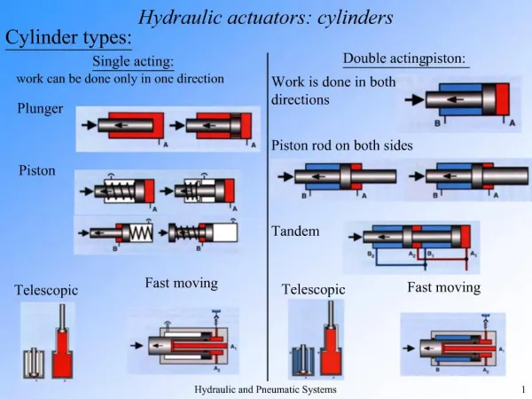
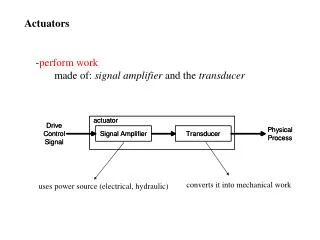
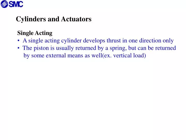
Cylinders and Actuators. Single Acting A single acting cylinder develops thrust in one direction only The piston is usually returned by a spring, but can be returned by some external means as well(ex. vertical load). Cylinders and Actuators. Single Acting

E N D
Cylinders and Actuators • Single Acting • A single acting cylinder develops thrust in one direction only • The piston is usually returned by a spring, but can be returned • by some external means as well(ex. vertical load)
Cylinders and Actuators • Single Acting • A single acting cylinder develops thrust in one direction only • The piston is usually returned by a spring, but can be returned • by some external means as well(ex. vertical load) • Advantages • lower air consumption compared to double acting • 3 way valve needed instead of 4 way (lower cost)
Cylinders and Actuators • Single Acting • A single acting cylinder develops thrust in one direction only • The piston is usually returned by a spring, but can be returned • by some external means as well(ex. vertical load) • Advantages • lower air consumption compared to double acting • 3 way valve needed instead of 4 way (lower cost) • Disadvantages • Reduction in piston thrust • Longer length body due to size of spring
Single Acting Spring Return Rest state. No pressure applied. Cylinder is retracted.
Single Acting Spring Return Rest state. No pressure applied. Cylinder is retracted. Air pressure applied. Cylinder extends. Spring is compressed.
Single Acting Spring Return Rest state. No pressure applied. Cylinder is retracted. Air pressure applied. Cylinder extends. Spring is compressed. Air pressure exhausted. Cylinder retracts due to the force of the spring and is returned to rest state.
Single Acting Spring Extend Rest state. No pressure applied. Cylinder is extended.
Single Acting Spring Extend Rest state. No pressure applied. Cylinder is extended. Air pressure applied. Cylinder retracts. Spring is compressed.
Single Acting Spring Extend Rest state. No pressure applied. Cylinder is extended. Air pressure applied. Cylinder retracts. Spring is compressed. Air pressure exhausted. Cylinder extends due to the force of the spring and is extended to rest state.
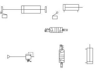
Double Acting Cylinders Thrust is developed in both extending and retracting directions as air pressure is applied to the appropriate ports.
Double Acting Cylinders • Thrust is developed in both extending and retracting directions • as air pressure is applied to the appropriate ports. • Advantages • More compact body when compared to single acting • Higher force with smaller bore size due to absence of spring
Double Acting Cylinders • Thrust is developed in both extending and retracting directions • as air pressure is applied to the appropriate ports. • Advantages • More compact body when compared to single acting • Higher force with smaller bore size due to absence of spring • Disadvantages • Force on retraction(piston rod side) is different than the • extension due to the reduced surface area where the • piston rod attaches to the piston
Double Acting Cylinder is at rest when neither port is energized. A B
Double Acting Cylinder is at rest when neither port is energized. A B When A is pressurized the piston extends out and B exhausts air.
Double Acting Cylinder is at rest when neither port is energized. A B When A is pressurized the piston extends out and B exhausts air. When B is pressurized, the piston retracts and A exhausts air. The cylinder is now back to its original state.
Variations in Cylinders Double Rod Type • Tandem Type 1 2 3
Variations in Cylinders Double Rod Type
Variations in Cylinders Double Rod Type • Tandem Type 1 2 3
Rodless Cylinders • Rodless cylinders can typically be installed in 1/2 the space of that of a standard cylinder. They are offered in much longer strokes and have higher side load capabilities.
Rodless Cylinders • Rodless cylinders can typically be installed in 1/2 the space of that of a standard cylinder. They are offered in much longer strokes and have higher side load capabilities. • Magnetically Coupled • The cylinder is coupled to the piston by magnetic force • requiring no physical attachment between the body • and the piston. Coupling permits smooth load transfer without allowing seal contamination.
Mechanically Coupled(Band Cylinder) • The cylinder is joined by a lip sealing mechanism suited for • very high loads while maintaining high accuracy. It • has much higher side load capabilities but is not as totally • leak free when compared to the magnetically coupled type.
Slide Units • Commonly used in very precision type applications which • require compact and low profile dimensions. Precisely • machined work mounting surfaces and parallel piston • guide rods ensure accurate and straight line movement.
Slide Units • Commonly used in very precision type applications which • require compact and low profile dimensions. Precisely • machined work mounting surfaces and parallel piston • guide rods ensure accurate and straight line movement. • Either the body can be fixed and the rods with end bars • can move or the end bars can be fixed and the body can • move
Air Chucks (Grippers) Designed to grip components using 2, 3, or 4 fingers
Rotary Actuators • Rack and Pinion Type • The output shaft has an integral pinion gear driven by a • a rack attached to a double piston. Standard angles of • rotation are 90° and 180°.
Vane Type • Air pressure acts on a vane which is attached to the • output shaft. The vane is sealed against leakage by • a lifted rubber seal or elastomer coating. Standard • angles of rotation are 90°, 180° or 270°.
Cushioning • In certain applications, it is necessary to specify air cushions • or shock absorbers due to high speeds and considerable • end of stroke forces.
Cushioning • In certain applications, it is necessary to specify air cushions • or shock absorbers due to high speeds and considerable • end of stroke forces. • Rubber Cushions • Often used on smaller size bore and stroke cylinders to absorb • shock and prevent internal damage.
Cushioning • In certain applications, it is necessary to specify air cushions • or shock absorbers due to high speeds and considerable • end of stroke forces. • Rubber Cushions • Often used on smaller size bore and stroke cylinders to absorb • shock and prevent internal damage. • Adjustable Air Cushions • Often used on larger size bore and stroke cylinders to decelerate • the piston over the last portion of the stroke. This cushion • traps some of the exhausting air near the end of the stroke • before allowing it to bleed off slowly through an adjustable • needle valve.
Special “Sine” Cylinder Cushion • Rapid load transfer whileallowing smooth acceleration • and deceleration of load which dramatically reduces • shock/impact.
Special “Sine” Cylinder Cushion • Rapid load transfer whileallowing smooth acceleration • and deceleration of load which dramatically reduces • shock/impact. • Shock Absorbers • Used for very high speed and heavy load applications • to consistently decelerate loads without requiring • additional adjustment. Can withstand impacts of • 16 ft/second.
Cylinder Options • Locking Cylinder • - Allows for +/- .5mm incremental stopping accuracy
Cylinder Options • Locking Cylinder • - Allows for +/- .5mm incremental stopping accuracy • Non-Rotating • - Prevents piston rod and the load from rotating
Cylinder Options • Locking Cylinder • - Allows for +/- .5mm incremental stopping accuracy • Non-Rotating • - Prevents piston rod and the load from rotating • Low Friction/Low Speed • - Special internal seals and lubricants allows speeds • of 2mm per second
Cylinder Options • Locking Cylinder • - Allows for +/- .5mm incremental stopping accuracy • Non-Rotating • - Prevents piston rod and the load from rotating • Low Friction/Low Speed • - Special internal seals and lubricants allows speeds • of 2mm per second • High Speed • - Enlarged orifices are added to maximize speed
Copper Free • - all components can be electroless nickel plated for • copper free environments
Copper Free • - all components can be electroless nickel plated for • copper free environments • High Temperature • - up to 300°F applications
Copper Free • - all components can be electroless nickel plated for • copper free environments • High Temperature • - up to 300°F applications • Low Temperature • - down to -58 °F applications
Copper Free • - all components can be electroless nickel plated for • copper free environments • High Temperature • - up to 300°F applications • Low Temperature • - down to -58 °F applications • Heavy Duty Rod • - enlarged piston rod for heavy side load applications
Copper Free • - all components can be electroless nickel plated for • copper free environments • High Temperature • - up to 300°F applications • Low Temperature • - down to -58 °F applications • Heavy Duty Rod • - enlarged piston rod for heavy side load applications • Adjustable Stroke • - allows final extension or final retraction to be • adjusted
Auto Switch Mount • - allows stroke feedback/conformation to controller to • confirm work has been completed
Auto Switch Mount • - allows stroke feedback/conformation to controller to • confirm work has been completed • High Magnetic Field Capability • - special auto-switches and internal magnets allow • cylinder to be used in applications 2” away • from magnetic field displacing 20,000 Amps
Determining Which Cylinder Bore Size to Use For a double acting cylinder: Extending Stroke: Fe = (p / 4) * D² x P Retraction Stroke: Fr = (p / 4) * (D²-d²) x P For a single acting cylinder: Extending Stroke: Fes = (p / 4) * D² x P - Fs D = Piston Diameter F = Force d = Piston Rod Diameter Fs = Spring Force at the End of Stroke P = Gauge Pressure