Download

1 / 63
660 likes | 878 Views
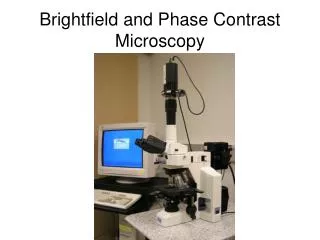
Brightfield and Phase Contrast Microscopy. Microscope: Micro = Gk. “small” + skopien = Gk. “to look at” . "Microscope" was first coined by members of the first "Academia dei Lincei" a scientific society which included Galileo. Microscopes. Upright Inverted Köhler Illumination

E N D
Microscope: Micro = Gk. “small” + skopien = Gk. “to look at”
"Microscope" was first coined by members of the first "Academia dei Lincei" a scientific society which included Galileo Microscopes • Upright • Inverted • Köhler Illumination • Dissecting (Stereoscopic) J. Paul Robinson – Purdue University
Euglena viridis - “green in the middle, and before and behind white”Antony van Leeuwenhoek - 1674
Earliest Microscopes • 1673 - Antioni van Leeuwenhoek (1632-1723) Delft, Holland, worked as a draper (a fabric merchant); he is also known to have worked as a surveyor, a wine assayer, and as a minor city official. • Leeuwenhoek is incorrectly called "the inventor of the microscope" • Created a “simple” microscope that could magnify to about 275x, and published drawings of microorganisms in 1683 • Could reach magnifications of over 200x with simple ground lenses - however compound microscopes were mostly of poor quality and could only magnify up to 20-30 times. Hooke claimed they were too difficult to use - his eyesight was poor. • Discovered bacteria, free-living and parasitic microscopic • protists, sperm cells, blood cells, microscopic nematodes • In 1673, Leeuwenhoek began writing letters to the Royal • Society of London - published in Philosophical Transactions • of the Royal Society • In 1680 he was elected a full member of the Royal Society, • joining Robert Hooke, Henry Oldenburg, Robert Boyle, • Christopher Wren J. Paul Robinson – Purdue University
So why are imaging systems needed? • Every point in the object scatters incident light into a spherical wave • The spherical waves from all the points on the object’s surface get mixed together as they propagate toward you • An imaging system reassigns (focuses) all the rays from a single point on the object onto another point in space (the “focal point”), so you can distinguish details of the object
Pinhole camera is simplest imaging instrument • Opaque screen with pinhole blocks all but one ray per object point from reaching the image space • An upside-down image is formed • BUT most of the light is wasted (it is stopped by the opaque sheet) • Also, diffraction of light as it passes through the small pinhole produces artifacts in the image
Imaging with lenses: doesn’t throw away as much light as pinhole camera Collects all rays that pass through solid-angle of lens
Refractive index is dependent on a ray of illumination entering a medium of differing density causing the beam to bend Classical optics: The refractive index changes abruptly at a surface and is constant between the surfaces. The refraction of light at surfaces separating media of different refractive indices makes it possible to construct imaging lenses. Glass surfaces can be shaped so that the angle at which the ray strikes it can differ.
In light optics this is accomplished when a wavelength of light moves from air (optical density of 1.0) into glass (O.D. 1.4 – 1.6).
Ray-tracing with a thin lens • Image point (focus) is located at intersection of ALL rays passing through the lens from the corresponding object point • Easiest way to see this: trace rays passing through the two foci, and through the center of the lens (the “chief ray”)
0.61 R.P. = ---------- N.A. Ernst Abbe 1840 - 1905 = wavelength of illumination N.A. = n (sine α) n = index of refraction α = half angle of illumination
In light microscopy the N.A. of a lens and therefore resolution can be increased by: a) increasing the half angle of illumination, b) increasing the refractive index of the lens by using Crown glass and c) decreasingthe wavelength () of illumination. 0.61 R.P. = ---------- N.A.
Object Resolution • Example: 40 x 1.3 N.A. objective at 530 nm light .00053 = 0.20 m = 2 x 1.3 2 x NA 40 x 0.65 N.A. objective at 530 nm light .00053 = 0.405 m = 2 x .65 2 x NA J. Paul Robinson – Purdue University
Images reproduced from: http://micro.magnet.fsu.edu/ Please go to this site and do the tutorials J. Paul Robinson – Purdue University
Microscope Objectives Standard Coverglass Thickness #00 = 0.060 - 0.08 #0 = 0.080 - 0.120 #1 = 0.130 - 0.170 #1.5 = 0.160 - 0.190 #2 = 0.170 - 0.250 #3 = 0.280 - 0.320 #4 = 0.380 - 0.420 #5 = 0.500 - 0.60 mm Microscope Objective 60x 1.4 NA PlanApo Oil Stage Coverslip Specimen J. Paul Robinson – Purdue University
Refractive Index Objective n = 1.52 n = 1.5 n = 1.0 Oil n = 1.52 Air n = 1.52 n=1.52 Coverslip n=1.33 Specimen Water n=1.52 J. Paul Robinson – Purdue University
The issues between simple and compound microscope • Simple microscopes could attain around 2 micron resolution, while the best compound microscopes were limited to around 5 microns because of chromatic aberration • In the 1730s a barrister named Chester More Hall observed that flint glass (newly made glass) dispersed colors much more than “crown glass” (older glass). He designed a system that used a concave lens next to a convex lens which could realign all the colors. This was the first achromatic lens. J. Paul Robinson – Purdue University
Converging (positive) lens: bends rays toward the axis. It has a positive focal length. Forms a real inverted image of an object placed to the left of the first focal point and an erect virtual image of an object placed between the first focal point and the lens.
Real and virtual image formation by biconvex lenses • Lens focal point • For an object further away than the lens focal point, an inverted, real image will be formed on the opposite side of the lens • For an object closer than the focal point, a virtual image will be formed on the same side of the lens • http://micro.magnet.fsu.edu/primer/java/lens/bi-convex.html
Diverging (negative) lens: bends the light rays away from the axis. It has a negative focal length. An object placed anywhere to the left of a diverging lens results in an erect virtual image.
Compound Microscope • The compound microscope uses at least two lens systems • The objective forms an intermediate real image of the object at the objective tube length • The ocular forms a virtual image of that intermediate image to the retina of the eye • If we are dealing with a photodetector, we must use a projection lens to form a real image from the intermediate image
The compound microscope differs from the simple, single lens microscopes in that it consists of a minimum three lenses (condensor, objective, and projector). Today the Objective lens is a multi-element lens, thus the number of lenses in a modern microscope can easily exceed 20.
Köhler • Köhler illumination creates an evenly illuminated field of view while illuminating the specimen with a very wide cone of light • Two conjugate image planes are formed • one contains an image of the specimen and the other the filament from the light J. Paul Robinson – Purdue University
Köhler Illumination eyepiece condenser Specimen Field stop Field iris retina Conjugate planes for image-forming rays Specimen Field stop Field iris Conjugate planes for illuminating rays J. Paul Robinson – Purdue University
Current microscope objective tend to be infinity corrected • Infinite tube length • Require an additional lens in objective to converge beam • Advantages • Objectives are simpler • Optical path is parallel through the microscope body:
Other lenses • Collector • Condenser • Allow us to use point light sources instead of parallel illumination • Also (later) increase the resolution of the microscope • Ironically, van Leeuwenhoek, who used simple non-compound, single-lens microscopes, was using the lens of his eye as a projection lens!
Light that passes both around and through the specimen undisturbed in its path is called direct light or undeviated light. The background light passing around the specimen is also undeviated light. Some of the light passing through the specimen is deviated when it encounters parts of the specimen. Such deviated light is rendered one-half wavelength or 180 degrees out of phase with the direct light that has passed through undeviated. The one-half wavelength out of phase caused by the specimen itself enables this light to cause destructive interference with the direct light when both arrive at the intermediate image plane at the diaphragm of the eyepiece. micro.magnet.fsu.edu/primer/anatomy/image.html
Lens Resolution • Geometric optics predicts lenses of infinite resolution • However, because of the phenomenon of diffraction, every point in the object is converted into an Airy disc • Diameter of Airy disc: D = 1.22 X λ / n sin α, or D = 1.22 X λ / NA
We cannot resolve objects whose Airy discs overlap by ~20% As a consequence, Abbe’s rule is that d=λ/NA http://micro.magnet.fsu.edu/primer/java/microscopy/airydiscs/index.html
Reading an objective http://micro.magnet.fsu.edu/primer/anatomy/specifications.html
For a typical 1.3 NA lens at 525 nm, the limit of resolution is ~ 400 nm • How to improve? • Larger NA (lenses, immersion fluid) • Shorter λ • Add a condensor: D = λ / (NAobj. + NAcond.) • So, for a 1.3 NA lens and condensor, D drops to ~200 nm
Abberations • Spherical aberration • Most severe • Immersion fluid • Field curvature • Chromatic aberration • Astigmatism, coma • http://micro.magnet.fsu.edu/primer/lightandcolor/opticalaberrations.html
Lens Defects The fact that wavelengths enter and leave the lens field at different angles results in a defect known as spherical aberration. The result is that wavelengths are brought to different focal points .
Spherical aberrations are worst at the periphery of a lens so a small opening aperture that cuts off the most offensive part of the lens is the easiest way to reduce the effects of spherical aberration but throws away a lot of the available illumination (i.e. pinhole camera)
Lens Defects Since the focal length f of a lens is dependent on the strength of the lens, if follows that different wavelengths will be focused to different positions. Chromatic aberration of a lens is seen as fringes around the image due to a “zone” of focus.
Lens Defects In light optics wavelengths of higher energy (blue) are bent more strongly and have a shorter focal length In the electron microscope the exact opposite is true in that higher energy wavelengths are less effected and have a longer focal length
The simplest way to correct for chromatic aberration is to use illumination of a single wavelength! Such illumination is called monochromatic .
Lens Defects In light optics chromatic aberration can be corrected by combining a converging lens of one O.D. with a diverging lens of a different O.D. This is known as a “doublet” lens
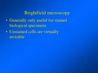
Brightfield microscopy • Generally only useful for stained biological specimens • Unstained cells are virtually invisible Brightfield Phase contrast