Download
1 / 34
340 likes | 476 Views
The BNL Super Neutrino Beam Project. W. T. Weng Brookhaven National Laboratory (presented by Milind Diwan) APS April Meeting ( T13 ) Tampa, Florida April 18, 2005. A. AGS Operation with protons B. Super Neutrino Beam Facility (1MW) B.1. New 1.2 GeV SCL B.2. AGS System Upgrade

E N D
The BNL Super Neutrino Beam Project W. T. Weng Brookhaven National Laboratory (presented by Milind Diwan) APS April Meeting ( T13 ) Tampa, Florida April 18, 2005
A. AGS Operation with protons B. Super Neutrino Beam Facility (1MW) B.1. New 1.2 GeV SCL B.2. AGS System Upgrade B.3. Neutrino Beam Production C. Cost Estimate and Schedule D. Further Upgrade Possibilities Conclusion Design report completed BNL-73210-2004-IR OUTLINE
AGS Intensity History 1 MW AGS
AGS high intensity/RHIC operation • AGS high intensity operation when RHIC is at store. • RHIC at store: presently ~ 85 hrs/week (50%), goal: ~ 100 hrs/week (60%) • Au – Au: • Typical 4-hour store length determined by Intra-Beam-Scattering (IBS) • Minimum refilling time is 5 – 10 minutes, typically takes < 1 hour • Fast injector switching between RSVP and RHIC mode beneficial • p – p: • Typical store length: 8 – 10 hours • Slower injector switching possible and necessary to ramp super-conducting AGS Siberian snake • Typical time to transition AGS from RHIC filling to high intensity proton ops ~30min. • Work in progress to go to 15 min. • Only incremental costs for high intensity operation. • High intensity and RHIC operations is very beneficial for equipment reliability and development of expertise. ~ 60-80 % of the time can be on AGS high intensity proton ops.
To RHIC To Target Station High Intensity Source plus RFQ 200 MeV Drift Tube Linac BOOSTER AGS 1.2 GeV 28 GeV 0.4 s cycle time (2.5 Hz) 200 MeV 400 MeV Superconducting Linacs 800 MeV 1.2 GeV 0.2 s 0.2 s AGS Upgrade to 1 MW • 1.2 GeV SCL extension for direct injection of 8.9 1013 protonslow beam loss at injection; high repetition rate possible. • 2.5 Hz AGS repetition ratetriple existing main magnet power supply and magnet current feeds, double rf power and accelerating gradient.
1.2 GeV SCL Typical DTL cycle for Protons 0.4 sec 0.4 sec 1 x 720 µs @ 30 mA AGS 0.6 sec 2.4 sec Booster 1.5-GeV Booster 28-GeV AGS 200-MeV DTL HI Tandem Two Injection Schemes
AGS Proton Driver Parameters • present AGS 1 MW AGS J-PARC • Total beam power [MW] 0.14 1.000.75 • Injector Energy [GeV] 1.51.2 3.0 • Beam energy [GeV] 24 28 50 • Average current [mA] 6 3615 • Cycle time [s] 2 0.4 3.4 • No. of protons per fill 0.7 1014 0.9 1014 3.3 1014 • Ave. circulating current [A] 4.2 5.0 12 • No. of bunches at extraction 6 23 8 • No. of protons per bunch 1 1013 0.4 1013 4 1013 • No. of protons per 107 sec. 3.5 1020 23 1020 10 1020
1.2 GeV Superconducting Linac • Beam energy 0.2 0.4 GeV 0.4 0.8 GeV 0.8 1.2 GeV • Rf frequency 805 MHz 1610 MHz 1610 MHz • Accelerating gradient 10.8 MeV/m 23.5 MeV/m 23.5 MeV/m • Length 37.8 m 41.4 m 38.3 m • Beam power, linac exit 17 kW 34 kW 50 kW Based on SNS Experiences
AGS Upgrade with CCL & SCL To RHIC To Target Station High Intensity Source plus RFQ 200 MHz DTL 800 MHz CCL BOOSTER AGS 1.2 GeV - 28 GeV 0.4 s cycle time (2.5 Hz) 116 MeV 400 MeV 800 MHz Superconducting Linac 1.5 GeV 0.2 s 0.2 s • Add CCL from 116 MeV to 400 MeV • SCL from 400 MeV to 1.5 GeV at 25 MeV/m gradient • One type of cavity, cryomodule, and klystron, similar to SNS.
B.2. AGS System Upgrades • Beam Dynamics in the AGS • Injection Painting • Linac Emittance improvement • Transition Crossing • Ring Impedances • Beam Collimation and Shielding • AGS Magnet Test • New Power Supply Design • AGS RF Cavity Design
AGS Injection Simulation • Injection parameters: • Injection turns 360 • Repetition rate 2.5 Hz • Pulse length 1.08 ms • Chopping rate 0.65 • Linac average/peak current 20 / 30 mA • Momentum spread 0.15 % • Inj. beam emittance (95 %) 12 p mm • RF voltage 450 kV • Bunch length 85 ns • Longitudinal emittance 1.2 eVs • Momentum spread 0.48 % • Circ. beam emittance (95 %) 100 p mm
Halo in AGS as Function of Linac Emittance For acceptable operation, the linac emittance has to be less than 1.5p Need to upgrade 750keV line 7 meters available 3 options studied
AGS New Transition Crossing • RF system: h=6 -> h=24; • (+) High acceleration rate: dB/dt increased from 2.2 to 7.2 T/s • (-) A large momentum spread is an issue – a result of the high RF voltage and large bunch area • Tolerable beam loss is about 0.25% at transition • The initial 95% bunch area needs to be reduced below 0.8 eVs
New AGS Main Magnet Power Supply • presently: • Repetition rate 2.5 Hz 1 Hz • Peak power 130 MW 50 MW • Average power 2.7 MW (FEB) 4 MW (SEB) • Peak current 5 kA 5 kA • Peak total voltage 25 kV 10 kV • Number of power converters / feeds 6 2
Eddy Current Losses in AGS Magnets For 2.5 (5.0) Hz: In pipe: 65 (260) W/m In coil: 225 (900) W/m
AGS RF System Upgrade • Use present cavities with upgraded power supplies • UpgradePresent • Rf voltage/turn 1.0 MV 0.4 MV • RF voltage/gap 25 KV 10 KV • Harmonic number 24 6 (12) • Rf frequency 9 MHz 3 (4.5) MHz • Rf peak power 2.7 MW 0.75 MW • Rf magnetic field 18 mT 18 mT • 300 kW tetrodes/cavity 2 1 • AGS/RHIC Operation Pulse-to-Pulse Same RF System modulation
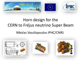
B.3 Neutrino Beam Production • 1 MW He gas-cooled Carbon-carbon target • New horn design • Target Hill for Radiation Protection • Target on 11.3 degree down-hill slope to aim at Homestake mine • Beam dump well above ground water table to avoid activation • Near Detector Beam Monitoring
E951 Results: ATJ Graphite vs. Carbon-Carbon CompositeThe results demonstrate the superiority of CC in responding to Beam SHOCK.The question is: Will it maintain this key feature under irradiation ???We will find out in the course of this irradiation phase Currently studying radiation effects On target materials
WHAT IS OF INTEREST TO US IN POST-IRRADIATION PHASE • Resilience in terms of strength/shock absorption • CTE evaluation • Stress-strain • Fatigue • Fracture Toughness and crack development/propagation • Corrosion Resistance • De-lamination (if a composite such as CC or plated HORN conductor) – Use of ultrasonic technology to assess changes • Resistivity changes • All of the above can/will be done in Hot Cell. • Other tests are also in the planning for scrutiny of the successful candidates (laser induced shock and property measurements)
Super Neutrino Beam Geographical Layout Super Neutrino Beam Geographical Layout BNL can provide a 1 MW capable Super Neutrino Beam the neutrino beam can aim at any site in the western U.S.; the Homestake Mine is shown here there will be no environmental issues if the beam is produced atop the hill illustrated here and the beam dumped well above the local water table construction of the Super Neutrino Beam is essentially de-coupled from AGS and RHIC operations
Neutrino Spectrum at 1 km Low Z (Carbon) target seemsfeasible for 1 MW, 28 GeV proton beam. Thin low Z target minimizesreabsorption which increases flux of high energy neutrinos
Homestake BNL 2540 km BNL Homestake Long Baseline Neutrino Beam Baseline Design: • 28 GeV protons from the AGS • 1 MW beam power from upgraded proton driver • 500 kTon Water Cherenkov Detector • Conventional Horn Focused beam • Alternate detector sites such as the WIPP facility in New Mexico and the Henderson mine in Colorado would be acceptable. The Homestake site is used for purposes of calculation.
Preliminary Cost Estimate – Continued • Total Direct Cost=$274 M • Add: • Contingency, 30% • BNL Project Overhead, 14.5% • Total Estimated Cost = $407 M
D. Further Upgrade Possibilities • Several possible upgrades, if combined, can provide 2 MW beam. • Increase the AGS repetition rate beyond 2.5 Hz. This can be accomplished by ramp down the AGS magnet in 0.1 sec, a • combined rep rate of 3.3 Hz. • Increase the AGS intensity to 1.3 x 10¹⁴ protons per pulse. To make this option possible, the SCL energy has to be increased to be 1.5 GeV. A better transition crossing system has also to be implemented. • A longer decay tunnel for capturing neutrino beam. • An improved hardonic beam focusing system
E. Conclusions • The feasibility has been demonstrated for a 1MW upgrade for the AGS • It is possible to further upgrade the AGS to 2 MW • Active R&D efforts are in progress to improve on the design and reduce cost. • The Total Estimated Cost is 407 M$ to complete the AGS upgrade and neutrino beam delivery system. • The construction can be completed in 5 years, with several years R&D efforts.
Beam Loss at H- Injection Energy • AGS Booster PSR LANL SNS 1 MW AGS • Beam power, Linac exit, kW 3 80 1000 50 • Kinetic Energy, MeV 200 800 1000 1200 • Number of Protons NP, 1012 15 31 100 100 • Vertical Acceptance A, pmm 89 140 480 55 • b2g30.57 4.50 6.75 9.56 • NP / (b2g3 A), 1012 / pmm 0.296 0.049 0.031 0.190 • Total Beam Losses, % 5 0.3 0.1 3 • Total Loss Power, W 150 240 10001440 • Circumference, m 202 90 248 807 • Loss Power per Meter, W/m 0.8 2.7 4.0 1.8 • ( Contro & Uncontrol )
Linac Emittance Improvement Emittance at source 0.4 pi mm mr (rms,nor)
Transient temperatures in the CC target subjected to a 100 TP, 28GeV 2mm RMS beam. Coolant temperature in the annular space The = 5 degree C