Download
1 / 24
240 likes | 399 Views
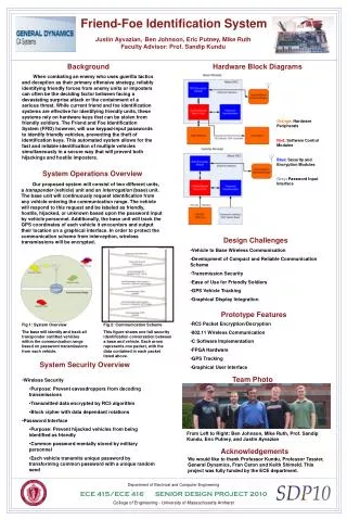
Friend-Foe Identification System. Justin Ayvazian Ben Johnson Eric Putney Michael Ruth Advisor: Professor Sandip Kundu. Project Overview and Motivation. Protect military personnel from hijacked friendly vehicles and hostile vehicles masquerading as friendly forces

E N D
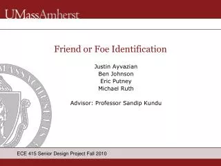
Friend-Foe Identification System Justin Ayvazian Ben Johnson Eric Putney Michael Ruth Advisor: Professor Sandip Kundu
Project Overview and Motivation • Protect military personnel from hijacked friendly vehicles and hostile vehicles masquerading as friendly forces • Reliably and quickly identify ground vehicles • Encrypted wireless transmissions for security • Password user interface • Display information and track vehicles on intuitive GUI
Benefits Over Current and Alternative Systems • Simultaneously and quickly handle multiple approaching vehicles • Not a data heavy transmission scheme • No physical hardware keys • Cannot steal the password • Data dependent encryption • Current system hacked by eavesdroppers • Vehicle tracking via GPS
System Block Diagrams Gray Blocks: Completed by CDR Red Blocks: Completed by FPR
From CDR • Completed: • RC5 encryption integrated with software • Ethernet communication between DE2 Boards • User password interface • To be Implemented: • Integrate GUI and DE2 Boards • Bridge Wireless communication between modules • Implement GPS hardware • Timeout and multi-vehicle handling • 802.11 System Simulation Data
Updated Hardware • Migration away from USB powered peripherals • Most USB products require O/S support for plug and play devices • Wireless Communication: • Quatech AirborneDirect™ Wireless Ethernet Bridge • Demo demonstrates 802.11b wireless connectivity • GPS Receiver: • San Jose Navigation EB-85A GPS Receiver • GPS Evaluation Board • RS232 connection for serial communication
GPS Interfacing • GPS Evaluation Board • RS-232 connection • EB-85A GPS Receiver • Geographic Position • NMEA Protocol • Eight minute Specificity • Baud Rate: 38400 bps • Changed from Holux GM-210 GPS Receiver • Required firmware drivers
GPS Protocol and Interfacing • GPS Module pushes NMEA sentences to board • GGA Sentence: $GPGGA,UTC,Lat,N/S,Lng,E/W,… • Comma delimited fields • Latitude Data: ddmm.mmmm • Longitude Data: dddmm.mmmm • Resolution: .0001/60 = 1.67 x 10^-6 degrees • GUI: 2 pixels = 1 m = X deg Lat, Y deg Lng • Prestore Base GPS, calculate difference in pixels between base and vehicle GPS to draw vehicle on GUI
Graphical User Interface • Issues: • Host computer to USB requires Plug-and-Play technology (operating system support) • JTAG Blaster only available communication method left for transmitting GPS coordinates to Google API • Unable to stream information over JTAG-Blaster • Corrections: • Custom made GUI • Use DE2 VGA protocols to stream to monitor • Stand alone system that requires no computer support
Wireless Communication Integration • AirborneDirect™ Ethernet Bridge • Point-to-point wireless communication • 802.11 b/g compliant • Changed from Quatech WLNG-ET-DP501 WiFi Access Point • Incompatible serial connectors for DE2 integration
Updated Message Structure • TCP/IP protocol used for packet transmission • Each message preceded by unencrypted TCP headers • Changed from UDP transmission • UDP not used by wireless bridges • Each packet payload transmitted will be 64 bits • Efficient for RC5 encryption scheme • Extra bits (where necessary) are randomly generated white noise for payload obfuscation. • Vehicle and base modules will have unique unencrypted IP address for routing and multi-vehicle handling • Allows base to throw out received TCP/IP packets not coming from a valid vehicle • Additional validation by cross-checking public and private IDs
Bandwidth Considerations • Transmitted data packets are 66 bytes • 8 byte payloads with 58 bytes of TCP/IP headers • Full conversation between vehicle and base is 462 bytes with appended TCP/IP headers • Assumes no collisions or lost messages • AirborneDirect Ethernet bridges have maximum bandwidth of 11 Mb/s • Must compete with all 802.11b devices in area • System can theoretically support hundreds of simultaneous conversations • Unable to physically test limit due to lack of hardware
FPR -Team Roles • Ben: RC5 encryption module and wireless communication • Mike: Packet composition and system implementation • Justin: GPS interfacing and system implementation • Eric: GUI and system implementation
Demo • GPS coordinates updated to GUI in real-time • Updated GUI scheme, integrated with DE2 Boards • Communication between GPS and vehicle module, base module and GUI fully integrated • Fully functioning wireless protocol • Bridged ad-hoc point-to-point communication • Communication and encryption modules completed • Password interface and encoding integrated on DE-II • 16 binary switches for password value with push button to simulate password submission • Password randomization function implemented • Multi-Vehicle Lookup Tables completed • Timeouts implemented for multi-vehicle handling
Experience Gained • Classes most useful to this project: • ECE 242, ECE 353, ECE 354, ECE 374 • Software used: • Quartus II, Nios II, Wireshark, Visual Studio C++ • Interactions with the professional engineering community • System engineering design process • Concept to functional prototype
Outcome Assessments • A: • ECE 242 - RC5 encryption algorithm. • ECE 353 – Firmware programming and hardware interfacing. • ECE 354 - FPGA system programming and NiosII C-based application programming. • ECE 374 – Ad-hoc communication scheme implemented with TCP/IP protocol. • B: • Created a meaningful GUI output simulating GPS coordinates. • Simulated base GPS and Vehicle GPS to ensure that the vehicle was displayed in expected location on the GUI. • Decomposed NMEA messages to ensure coordinates obtained by the GPS module matched Google Maps • Analyzed raw GPS data and compared to previous known results to debug our GUI. • Wireshark used to decompose 802.11 packets for ethernet bridge integration and testing.
Outcome Assessments • C: • I • Fast and reliable wireless communication up to one mile • Multi-Vehicle handling • Secure transmission scheme • Password interface that will attempt to prevent the vehicle from being able to be hijacked. • II • Prototype constrained to 100 meter range • Limited connection methods to DE2 boards • III • Developed simplified and secure password system that will prevent hijacked vehicles from being identified as friendly in all but the most extreme scenarios
Outcome Assessments • D: • Justin Ayvazian (EE) • GPS unit integration • Decomposition of GPS messages and scaling for the GUI. • Ben Johnson (CSE) • Implementation of RC5 encryption algorithm • Configuration and integration of wireless Ethernet bridges. • Eric Putney (CSE) • System integration • Creation and updating of GUI • Mike Ruth (CSE) • Packet composition and decomposition • Creation and analysis of data messages. • All members worked together on the code that runs the vehicle and base modules. Each module consists of a state machine that runs and integrates all of the separate components. These state machines were a group effort.
Outcome Assessments • E: • Outputting over the USB blaster would not be possible: • Alternative output GUI would need to be developed. • Done by designing our own GUI that would output over a VGA cable directly into a monitor. • Helped in making our system standalone which improved the system design.
Outcome Assessments • F: • System reliability: • Safety of soldiers reliant on system • Exclusive testing was required • G: • Email and phone while apart • Vocally while together
Outcome Assessments • H: • Prevention of Vehicle hijackings and bombings • Comfortable environment for soldiers and families • Negative consequences: • Mal-intent, deception, and destruction by terrorist groups • I: • RC5 Encryption • Encryption of wireless transmission data • NMEA protocol • Proper interfacing with GPS antenna • WiFi packet structure • Interfacing wireless Ethernet bridges
Outcome Assessments • J: • Safety of soldiers • Eliminate threats at checkpoints • Saves lives • K: • Quartus • Compilation and Synchronization of DE2 Boards • NIOS II • C/C++ software implementation • Wireshark • Network protocol analyzer