Download
1 / 14
150 likes | 248 Views
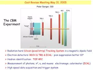
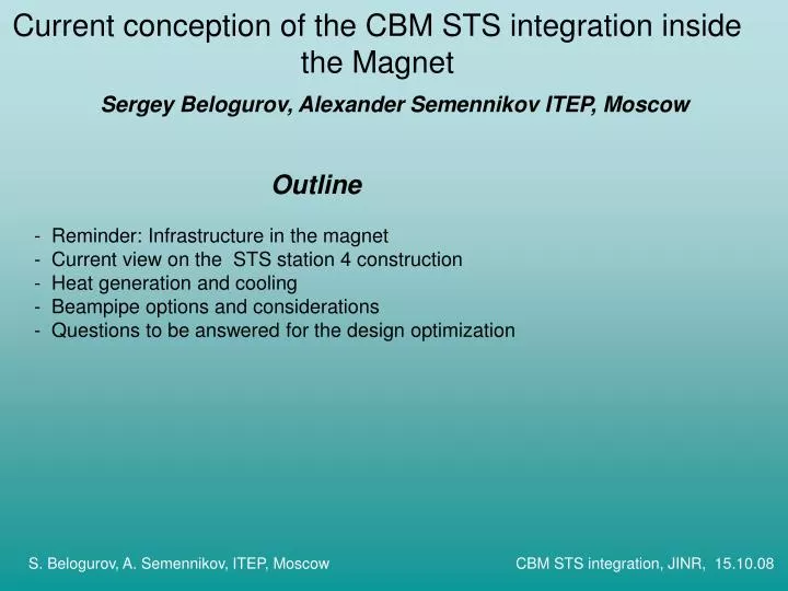
Current conception of the CBM STS integration inside the Magnet. Outline Reminder: Infrastructure in the magnet Current view on the STS station 4 construction Heat generation and cooling - Beampipe options and considerations

E N D
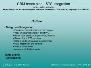
Current conception of the CBM STS integration inside the Magnet • Outline • Reminder: Infrastructure in the magnet • Current view on the STS station 4 construction • Heat generation and cooling • - Beampipe options and considerations • Questions to be answered for the design optimization Sergey Belogurov, Alexander Semennikov ITEP, Moscow S. Belogurov, A. Semennikov, ITEP, Moscow CBM STS integration, JINR, 15.10.08
Reminder: Infrastructure in the magnet • Hierarchy: Module – half station – half STS – thermoinsulated volume • Realistic cooling: Power estimation(1.5 W/chip @ 1.5 V; 70 W/module),local cooling: heat conductivity (Al: 235 W m-1 K-1) and liquidC6F14 (LHCb, CMS) The space inside the magnet (Thanks to E. Matyushevsky and E. Litvinenko) is supposed to be thermoinsulated by a closed shell A section of the beampipe just before the magnet, approx 1.5 m long can be dismounted thus allowing to pull out the thermoinsulated box (see the flange). S. Belogurov, A. Semennikov, ITEP, Moscow CBM STS integration, JINR, 15.10.08
Current view on the STS station 4 construction Starting point: Design by S. Igolkin presented in Protvino and further discussions in GSI thisSeptember. Duralumin milled frame and heat sinks 1/4 of the station and a single module S. Belogurov, A. Semennikov, ITEP, Moscow CBM STS integration, JINR, 15.10.08
Current view on the STS station 4 construction Ruby ball and spring fixation to avoid stress Cooling plate with soldered tubes and aluminum heat sink Size of the “bounding box” (envelope) is defined conservatively with C. Schmidt S. Belogurov, A. Semennikov, ITEP, Moscow CBM STS integration, JINR, 15.10.08
Current view on the STS station 4 construction two thermally insulated regions of cooling, sensors with cold nitrogen, RO electronics with liquid S. Belogurov, A. Semennikov, ITEP, Moscow CBM STS integration, JINR, 15.10.08
Current view on the STS station 4 construction • Stepped positioning of the heat sink (basic module concept): • Limited number of the cables types • Horizontal FE boards: • Less height but bigger thickness (11 cm per station if the board size does not decrease) S. Belogurov, A. Semennikov, ITEP, Moscow CBM STS integration, JINR, 15.10.08
Current view on the STS station 4 construction Flexible tube connection to the trunk line, Tube diameter - turbulent flow – liquid bellow the atm. Pressure? S. Belogurov, A. Semennikov, ITEP, Moscow CBM STS integration, JINR, 15.10.08
Heat generation and cooling of the sensors Fluence distribution over the position of the 4-th STS station and its projection over the beam axis. Thanks to D. Bertini S. Belogurov, A. Semennikov, ITEP, Moscow CBM STS integration, JINR, 15.10.08
Heat generation and cooling of the sensors Depletion voltage dependences on the neutron equivalent fluence where I(T)=R(T)I(T0), and T0 stands for 293.15 K . Leakage current per unit volume vs. neutron equivalent fluence recalculated to 20°C and to annealing at 60 °C for 80 min. S. Belogurov, A. Semennikov, ITEP, Moscow CBM STS integration, JINR, 15.10.08
Heat generation and cooling of the sensors Operation at -10°C would give heat power decrease by factor about 15 (factor 5.6 for 0°C) . Taking into account the thermal runaway issue and desirable operation time of few years it makes sense to design cold nitrogen cooling system capable of taking away the shown power S. Belogurov, A. Semennikov, ITEP, Moscow CBM STS integration, JINR, 15.10.08
Heat generation and cooling of the sensors Distribution of the temperature of the sensors and the gas. Sensors in plane, 1-10 mW/cm2. Laminar flow ~1.5 m/s. First consultations with the refrigiration experts show, that such a cooling is possible in principle. Experience of LHCb IT, STAR, SVD : worth studying but not directly applicable Feasibility study and thermal prototype are required (when, where, who will pay?) S. Belogurov, A. Semennikov, ITEP, Moscow CBM STS integration, JINR, 15.10.08
Beampipe options and considerations Potential manufacture: The Be institute of the JSC “Kompozit”, Korolev, Moscow region. Has produced 11 m long (3 sections) beampipe for LHCb with diameter up to 270 mm. Currently ITEP represents CERN in the preparation of the last section upgrade Be beampipe: the general sketch S. Belogurov, A. Semennikov, ITEP, Moscow CBM STS integration, JINR, 15.10.08
Beampipe options and considerations The alternative to Be is CF reinforced plastic. Russian manufacturer (2m wheels for ATLAS, contacted through IHEP) rejected the job. It is necessary have a first feed back from the IVW (Institute for composite material research Kaiserslautern, Germany) The main points for the comparison: min. feasible thickness and price (0.5-0.7 mm and ~150 k Euro for Be) S. Belogurov, A. Semennikov, ITEP, Moscow CBM STS integration, JINR, 15.10.08
Questions to be answered for the design optimization • By the magnet designers: Field map and the magnet price for the gap height of a) 1150 mm b)1450 mm For each of the cases it is important to see the zero field regions for placing the power adaptors. • By the STS tracking group: Is the mapped field acceptable for the tracking or more complicated correcting coils should be investigated? What would be negative effect of the tubes with cooling liquid along the ladders? • By the RICH group: What effect on the RICH efficiency would the stray field have for each of the cases? Answers to such questions will help us to make a decision about the magnet and the STS infrastructure design especially at the zone of the last stations S. Belogurov, A. Semennikov, ITEP, Moscow CBM STS integration, JINR, 15.10.08