Download
1 / 90
1.02k likes | 1.34k Views
RTTY. A Primer on the Second Digital Mode Plus a bit of PSK K2YG Jan 9, 2012. History. The first digital radio mode was make/break spark gap transmission, followed by CW, or more properly, Morse or any other on/off switching code over a CW (continuous wave or carrier wave) radio signal.

E N D
RTTY A Primer on the Second Digital Mode Plus a bit of PSK K2YG Jan 9, 2012
History • The first digital radio mode was make/break spark gap transmission, followed by CW, or more properly, Morse or any other on/off switching code over a CW (continuous wave or carrier wave) radio signal. • Teletype over wires started in 1849 • Emile Baudot (baw-DOUGH) invented modern 5 bit TTY code in 1874; still used today
RTTY (Radio Teletype) History • First radio use in the 1920s • First commercial use in the 1930s • Military use started in the 1930’s and replaced on-off signal with two tone frequency shift. • TTY and RTTY in various forms were the backbone format for information transmission until superseded by computer systems.
History in Amateur Radio • 1946: First contact; used make-break keying. • Frequency Shift (FSK) found to be superior in late 40’s, but not allowed by FCC regulations. • FCC allowed FSK in 1953 • Bulky noisy teleprinters supplanted by personal computers in the 80’s, beginning the explosion in Amateur RTTY and other formats. • Click here to hear what RTTY sounds like:
What is RTTY • Radio Teletype is the transmission and reception of Baudot coded text over radio links using Frequency Shift Keying. • The Baudot code characters consist of start and stop bits, with five information bits in-between.
Baudot Code Logic 1 or Mark 0 or Space Character: Y Can also be 6 Bit 1 Bit 2 Bit 3 Bit 4 Bit 5 Character: R Can also be 4 Logic 1 or Mark 0 or Space Bit 1 Bit 2 Bit 3 Bit 4 Bit 5 Character: B Can also be ? Logic 1 or Mark 0 or Space Bit 1 Bit 2 Bit 3 Bit 4 Bit 5 Logic 1 or Mark 0 or Space Character B showing start and stop bits Start Bit Bit 1 Bit 2 Bit 3 Bit 4 Bit 5 Stop Bit
RTTY Speed • Amateur RTTY usually operates at a speed of 45.45 baud, or approximately 60 words per minute. Other speeds are occasionally used, such as 50 and 75 baud. Commercial RTTY services (very few left) may use other rates and frequency shifts. • Baud rate is the number of symbols per second. Each mark or space is a symbol.
Baudot Register Shifting • 26 Letters, 10 numbers and a few punctuations and control codes require more than the 32 combinations possible with 5 binary bits. • 59 letters, numbers, punctuation, symbols and functions are possible by using two shift registers.
Shift Characters in Place • To transmit characters from both shifts, shift codes are inserted automatically in the string: K FIGS 2 LTRS Y G • In this case, six 5 bit characters are required to transmit the 4 characters typed. • Special characters include space, line feed, carriage return and up and down shift. • Once shifted, shift usually stays in FIGS until LTRS character is sent, and vise versa.
Garbled Shift Characters Signal report sent with good vs. garbled up-shift (FIGS) character. Good Garbled RST 599 RST TOO K2YG KWYG This is a very common occurrence. QWERTY keyboard relationship on next slide.
Figures-shift numbers on the top line of the keyboard correspond to the second line letters located below & a bit to the right of each number Thus a missed FIGS shift would cause the 599 to print as TOO
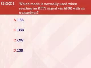
RTTY Keying Methods • Two Methods: Frequency Shift Keying (FSK) and Audio Frequency Shift Keying (AFSK) • FSK shifts an un-modulated carrier between two radio frequencies usually spaced 170 hz . • AFSK modulates an SSB signal using two 170hz spaced tones which simulate the FSK signal. • FSK has very few RF artifacts. AFSK can have suppressed sideband and carrier leakage, as well as modulation products, so proper transmit audio level is important.
RTTY Keying Methods • AFSK: Characters typed are converted by software and a sound card into two audio tones to be fed to microphone or data connections on the transmitter. • FSK: Characters typed are converted by software into a make-break control voltage which keys a shift in the transmitter carrier radio frequency.
Audio Tones and RF Relationship RF Readouts for Audio Frequency Shift Keying (AFSK) vs. Frequency Shift Keying (FSK) 20 Mtrs, Lower Sideband. Space Mark Suppressed (2295 hz) (2125 hz) Audio Tones Carrier (0 hz) 14082.705 14082.875 RF Carriers 14085.000 khz khz khz FSK shows mark or space RF frequency on radio readout. AFSK shows suppressed carrier frequency on readout. AFSK FSK
Receiving RTTY is really AFSKbecause the computer sound card and software convert the audio tones you hear into characters Space Mark Suppressed (2295 hz) (2125 hz) Audio Tones Carrier (0 hz) 14082.705 14082.875 RF Carriers 14085.0 khz khz khz AFSK FSK
RTTY Waveform Time Mark Amplitude Zero Amplitude at frequency shift Space Amplitude
RTTY Customary Operating FrequenciesBand General Contests 160 1800-1820 Unusual 80 3580-3600 3565-3600 40 7040-50, 80-100 7030-7100 30 10140-10150 NA 20 14080-14099 14060-14140 17 18100-18110 NA 15 21080-21099 21065-21140 12 24920-24930 NA 10 28080-28100 28065-28140
RTTY Band Non-Contest PopularityBand General Usage 160 1800-1820 Infrequent 80 3580-3600 A few nets 40 7040-50, 80-100 Moderate 30 10140-10150 Growing 20 14080-14099 Most Popular 17 18100-18110 Good when open 15 21080-21099 Heavy use if open 12 24920-24930 Surprisingly good 10 28080-28100 Excellent if open On all bands from 40 to 10, there will be more PSK than RTTY activity except during contests and presence of rare DX.
Frequencies to Avoid • Avoid PSK segments at 7037-7040, 14070-14073 , 21070-21073, and 28120-28123. • Avoid Internation Beacon Project beacons (18) at 14100, 18110, 21150, 24930, & 28200. • FCC Regulations actually allow HF data operation on any amateur frequencies on which Phone is NOT allowed.
License Level Restrictions? • Notice that, contrary to CW and SSB operation, General Class license holders can operate on all customarily used RTTY frequencies. • Novices & Techs can operate digital (as well as CW & SSB) on 10 Meters.
Simplex vs. Split Operation • Split operation by DX stations is more frequent on RTTY because of qrm by calling stations. • Even moderately rare DX stations may operate split to improve QSO rate. • Operating split sometimes involves only two frequencies: the DX qrg and a calling qrg up one or two khz. Rare DX split may occupy 10 khz or more. Study the DX listening pattern before calling. Calling frequencies are usually up. • Split operation is extremely rare in contests.
REMEMBER THIS If you take home only one thing from this presentation, make it the link to AA5AU’s RTTY Home Page http://www.aa5au.com/rtty.htm Contains complete information on setting up and operating RTTY, and MMTTY software Also, join RTTY Contesting as a source for help. http://lists.contesting.com/mailman/listinfo/rtty
RTTY Software • MMTTY – Most Popular? – Free • Write Log (not free) • Ham Scope • Mix W • RCK RTTY (not free) • RITTY – Not supported, not free but not sold anymore, DOS only, but is the best receiving program in existence (my opinion). • There are many programs available. I am familiar only with MMTY and RITTY. • Talk to other digitally active club members: K2EZR, KB2FCV, N2FYE, K2GLS, K2MUN,KC2WUF
Hardware you need to run RTTY Radio Computer with Sound Card Interface
RADIO Considerations • Any TX/RX capable of SSB will work. • Some can run RTTY, a key down mode, at full power; some can not. Check specs. • Filter adaptability is important. Will the SSB filters allow a band pass centered on RTTY tones. (2125 + 170/2 = 2210 khz center qrg). Alternate tones can solve this problem, but may cause others. • FSK capable TX/RX usually do not have filter band pass problems
Computer • Most currently supported RTTY software will run on Windows XP, Vista and 7. There are programs for other operating systems. • Programs are not too demanding of processor and memory, but combined with logging programs like N1MM or Writelog memory and speed requirements increase. • Computers w/o serial port will require either a USB serial adapter for PTT or use of “vox”. • Resistance to RFI is important.
Interfacing Computer to Radio Buy a commercially available interface, such as Signalink, Rig-expert, Rigblaster, etc. -or- Build your own. Might be a good club project!
Home Brew AFSK Interfacing CQ CQ DE K2YG K2YG K K2YG DE ST0R 599 599 K2YG RX Audio Radio audio out to Computer audio in. PTT Line May require a USB to Serial Adapter TX Audio Computer audio out to radio mic. Mayneed some isolation or attenuation
Home Brew Interface Transmit Interface connects between computer audio out and mic connector Isolation Transformer 10k ohms RF Bypass Capacitor 100 ohms From Computer Audio Out To TX Mic Connector RF Bypass Capacitor Transformer and capacitors needed only to resolve rf interference, audio hum, and other artifacts. Potentiometer can replace resistors.
Receive Interface • Receive audio can be connected directly from radio head phone, speaker, or dedicated constant level audio output if available. • Isolation transformer and by pass capacitors may be helpful.
PTT Circuit Computer Serial Radio PTT Line Connector (Probably in Mic Connector) PTT circuit using single transistor. A USB to serial adapter is needed if computer has no serial port; or use VOX (not recommended for contesting).
FSK Interfacing • Interfacing for FSK operation requires a transistor switching circuit similar to the PTT line shown before, connected between the computer serial or USB port and the FSK capable radio’s FSK input, instead of the TX audio line to the mic input. This is more problematic than AFSK if a USB to serial adapter must be used because of baud-rate specifications of USB adapters available.
MMTTY - RTTY Software • Software written by JE3HHT, Makoto Mori, thus the program name. It is free and downloadable from: http://hamsoft.ca/pages/mmtty.php • Excellent instructions and other RTTY advice is available at http://www.aa5au.com/rtty • Screen looks like:
Demodulator Section displays most set up parameters such as filter, tuning, shift, and squelch control.
Control section: Manual transmit/receive toggle and some RTTY decoding options.
Macros: user pre-entered text sent by clicking buttons or using F keys and Control key plus numbers
QSO Data, for automatic insertion in Macro qso content, and for log entry
This is the way the Demodulator box should appear after opening MMTTY. Mark and Shift are set to standard RTTY values. In this setting, the Bandpass Filter (BPF) Squelch (SQ) and Automatic Frequency Control (AFC) have been turned on by the user.