Download
1 / 16
160 likes | 294 Views
Sacrificial Anodes used for Transformer Housing Protection. INTERIM REPORT. Prepared by: Ms.Pranoti Kadam Advisers: Prof. Zivan Zabar Prof. Walter Zurawsky Date: June 19, 2009. Visit to ConEdison (Astoria & Transformer Site ) Dates: 8 th April & 27 th April’09.

E N D
Sacrificial Anodes used for Transformer Housing Protection INTERIM REPORT Prepared by: Ms.Pranoti Kadam Advisers: Prof. Zivan Zabar Prof. Walter Zurawsky Date: June 19, 2009
Visit to ConEdison (Astoria & Transformer Site )Dates: 8th April & 27th April’09 • Number of Sacrificial anode attached to the tank. • Availability of a Remote Monitoring System (RMS) for transformers. • All sacrificial anodes are connected to the neutral of the transformer. • The tank at the site was half filled with water, soil and trash. • No sacrificial anode was placed at the bottom of the tank touching the floor of the vault.
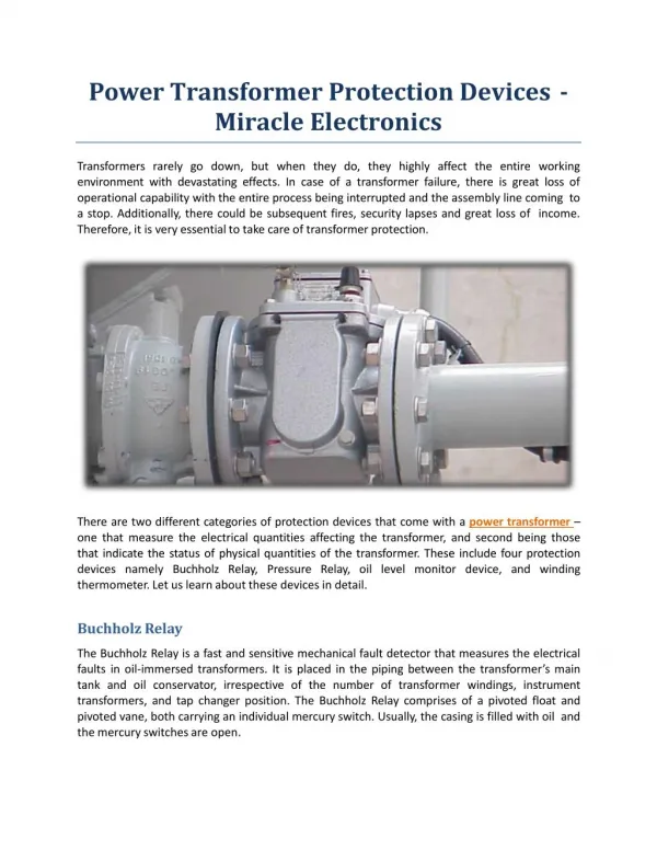
Corrosion (short review) It is the process of Oxidation. i.e the metal undergoes a continues decomposition forming ions. Oxidation: Fe -------> Fe+2 + 2 e- IRON FERROUS IONS (Black) Fe+2 ------> Fe+3 + 1 e- FERRIC IONS (Red) O2 (g) + 2 H2O + 4e- ------> 4 OH- HYDROXYL IONS 4Fe+2(aq) + O2(g) + [4 + 2 x H2O (L)]-------> 2Fe2O3 X H2O(s) + 8H+(aq) RUST
Cathodic Protection It is a method of preventing corrosion of the metal surface by making it cathode of an electrical circuit. Oxidation: (Eg: Zinc) Zn -------> Zn+2 + 2 e- O2 (g) + 2 H2O + 4e- ------> 4 OH- 4Zn+2(aq) + O2(g) + [4 + 2 x H2O (L)]-------> 2Zn2O3 X H2O(s) + 8H+(aq) Also if; Fe----------> Fe+2 + 2 e- Again, Fe+2 + (e- from Zn) 2 e- ------------------> Fe
Experiment • The experiment was performed on two specimens of tank provided by Con Edison including one extremely corroded piece, and other slightly corroded, using Zinc anode. • Plain water was used as an electrolyte, the sacrificial anode-Zn; cathode-Fe and the reference electrode-Cu; placed in water during the test. • The experimental setup was made with reference to the US patent 5,999,107 and 5469,048
Considering Vcb1 be the voltage between the cathode Fe and the reference electrode Cu when the sacrificial anode is connected to the cathode and Vcb2 be the voltage between the cathode Fe and reference electrode when the sacrificial anode is disconnected from the cathode. • Verification -1 A document E-2 by American Boat & Yacht Council states that the difference between these two voltages Vcb1 & Vcb2 should be greater than 200mV; thatindicates the cathodic protection is active and is sufficient for the protection. • When the sacrificial anode is in the circuit , the voltage between the cathode and reference electrode has a higher value due to the voltage caused by the resistances of the metal and lead connections. • When the sacrificial anode is suddenly removed from the cathodic protection, the voltage due to the resistance of the connections is zero and we get the actual open circuit potential between the cathode and th reference electrode. This voltage is known as the tank to water potential. • Verification -2 When the cathode Fe is suddenly disconnected from the sacrificial anode Zn, the polarized cathode further depolarizes, thereby causing the decay or decrease in the measured tank to water potential. • A minimum negative polarization voltage shift of 100mV is often specified to indicate adequate cathodic protection (Ref. patent 5469048).
Exp.A Exp.B
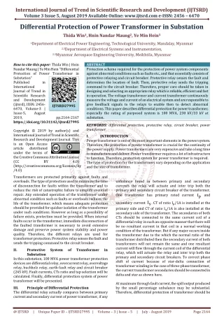
Readings for the voltage between cathode and ref. electrode and current flowing from sacrificial anode to cathode.
Voltage drop when sacrificial anode in not connect to the cathode
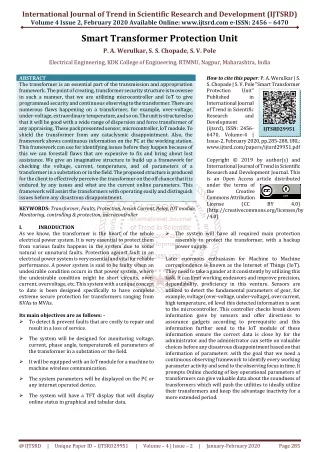
Results Measured outputs: • The voltages between the reference electrode Cu and the tank Fe with and without the sacrificial anode (Cases 1, 2, 3 are values of voltages and currents at different time intervals). • ‘IR’ voltage drop free Tank Fe to water Cuvoltage measurement. • Corrosion current of the sacrificial anode.
Observations: • Voltage comparison between the reference electrode and the tank with and without sacrificial anode in the circuit gave a difference of more than 200mV. • Corrosion current of the sacrificial anode was measured , when the current in the 2 eaperiment conditions were compared it was found that in the case1,at the starting point of cathodic protection the piece highly corroded draws more current than the piece slightly corroded. • In case 2 after two days with the same condition, the current further reduces as by then the cathode is under stable protection conditions. • In the case 3 the amount of electrolyte was increased which caused the current to increase further. Conclusions from the outputs: • The amount and type of electrolyte has an effect on the rate of corrosion. • The effectiveness of the sacrificial anode can be determined. • Corrosion level of the tank may be determined using the amount sacrificial anode current ???
Future Work • As a part of future studies , the values of voltage and current of two different specimens in same electrolyte will be studied. • The effect on the experiment readings with different types of electrolyte needs to be studied. • Need to obtain the limits for the sacrificial anode current to compare the level of corrosion using outputs of several experiments combinations , and try to interpret this data to determine the level of corrosion of the iron. • Perform the same experiment with same piece of cathode, but use a number of anodes instead of one, and compare the currents. • Perform the experiment on the real tank in real conditions. • Suggestion from Con Edison engineers are welcome.