Download
1 / 54
540 likes | 662 Views
LCLS Status and Micro-Bunching Workshop at LBNL. Torsten Limberg. Workshop Home Page. Workshop 0: ‘S2E & Instabilities’ in Zeuthen 2003. Zeuthen 2003. Laser ‘Heater’. Gain Calculations Zeuthen 2003. More Gain Calculations Zeuthen 2003. Back to LBNL Workshop: ‘Presentations’ Page.

E N D
LCLS Status and Micro-Bunching Workshop at LBNL Torsten Limberg
Talk Layout • Tour Through the Workshop Program • The LCLS COTR Problems and its Laser Heater • LCLS Status
Program… Microbunching Workshop II – LBNL, 6-8 October, 2008 Semi-Final Program Schedule [last updated 2 October 2008] Monday, 6 October Introduction 9:00 – 9:20 • 9:00-9:05 Welcome, S. Gourlay, LBNL AFRD Head • 9:05–9:20 Workshop Goals + Facilty Info. “Nuts & Bolts”, W. Fawley, LBNL • Session I - Observations of Microbunching 9:20-12:30 Chairman: M. Cornacchia • 9:20-9:50 Microbunching Observations at LCLS -- Z. Huang, SLAC • 9:50-10:20 Microbunching Observations at FLASH -- B. Schmidt, DESY • 10:20-10:50 Investigation of Microbunching Instability at the SCSS test accelerator -- K. Togawa, SPRING-8 • 10:50-11:40 Discussion & Coffee Service • 11:40-12:10 Studies of fragmentation in electron beam energy spectra at SDL –- T. Shaftan, BNL • Laser pulse shaping and beam structures at SDL -- S. Seletskiy, BNL • 12:10-12:40 COTR and SASE from Compressed Beams -- A. Lumpkin, FNAL
Program… Session II - Theory and Simulation 14:00 - 18:00 Chairs: A. Zholents (pre-break) & G.Stupakov (post-break) • 14:00-14:30 Overview and Recent Progress in uBI Theory and Simulation S. DiMitri, Trieste 14:30-15:45 Contributed talks on uBI Theory and Simulation: • Modeling uBI Growth in the SPARX Configurations, C. Vaccarezza, INFN/Roma • Nonlinear Correction to the Gain of the Microbunching Instability Seeded by Shot Noise, M. Venturini, LBNL • Large-Scale Simulation of Microbunching Instability in the Berkeley FEL Linac Studies, J. Qiang, LBNL • A Vlasov-Maxwell Solver to Study Microbunching Instability in the FERMI@ELETTRA First Bunch Compressor System, G. Bassi, Daresbury; J. Ellison, UNM; K. Heinemann 16:45-17:20 Contributed Talks on uBI Simulation + Modeling Existing Experiments: • Wisconsin FEL Bunch Compressor Modeling, R. Bosch, U. Wis. • Accelerator Design Concepts and Simulation Issues Relevant to the Microbunching Instability, Y. Kim, PSI • Unrecognized Singularity in the Field of a 1-D Evolving Bunch, R. Warnock, SLAC • LSC Microbunching from Shot Noise and Comparison with LCLS Results, D. Ratner
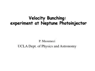
Program… Session III - Cathode, Laser, & Injector Physics Relevant to uBI Initialization & Growth 9:00 - 12:30 Chairperson T. Limberg • 9:00-9:30 Cathode Emission Physics and Origins of Non-uniformity – K. Jensen, NRL • 9:30-10:00 Laser Photocathode Physics & Observations Relevant to μBI -- D. Dowell, SLAC • 10:00-10:30 Post-cathode Dynamical Evolution of E-beam Non-Uniformities -- P. Piot, NIU/Fermilab • 11:15-12:30 Contributed talks on uBI Initialization & Growth in Cathode/Injector Regions: • Possible Sources of Non-Uniform Emission ,no, Velocity Bunching!, M. Ferrario, INFN/Frascati • 3D Study of Effects from Inhomogeneities upon the Minimum Achievable Emittance, M. Quattromini, NEA/Frascati • Microbunching Instability in Velocity Bunching, D. Xiang, SLAC • Simulation of Propagation of Cathode Region Modulations in the FERMI Injector, • G. Penco & P. Craievitch, Sincrotrone Trieste
Program… Session IV - Diagnostics & Control 13:30-17:45 Chairpersons, D. Dowell (pre-break) & M. Ferrario (post-break) • 13:30-14:15 Current state-of-art in OTR physics & diag. setup – R. Fiorito, U Md., & A. Lumpkin, FNAL • 14:15-14:40 LCLS OTR setup and COTR studies – H. Loos, SLAC • 14:40-15:05 COTR observations at FLASH – B. Beutner, PSI • LCLS Laser Heater plans – P. Emma, SLAC • FERMI Laser Heater plans – S. Spampinati, Sincrotrone Trieste • 16:00-17:15 Contributed talks on Diagnostics and Control: • E-beam High-Frequency Content on the Bunch Length Measurement and • Longitudinal Feedback, J. Wu, SLAC • Two Stage, Single Shot IR CTR Spectrometer, S. Wesch, DESY • Compressing Electron Bunches with Solenoids, A. Zholents, LBNL • COTR Mitigation with a Tilted OTR Foil, G. Stupakov, SLAC • 17:15-17:45 Discussion
Program… • Near-Term Future Plans at Different Labs • 9:00-10:20 Plans @ different labs including expt. verification/benchmarking of uBI theory & • simulation, followed by open general discussion • DESY FLASH & XFEL plans – T. Limberg • FERMI Plans -- Injector microbunching characterization using a low energy deflecting cavity • BNL plans – S. Seletskiy • Frascati Plans - M. Ferrario • ANL/FNAL Plans, A. Lumpkin • Shanghai plans for uBI expt. studies– Z. Huang, SLAC, speaking for D. Wong, Shanghai • Microbunching Experimental Plans at the Upcoming PSI 250 MeV injector – Y. Kim, PSI • Daresbury Plans --- P. Williams
The LCLS COTR Problem OTR Screens downstream of ‘dogleg’ not usable with design machine parameters No COTR High gain COTR Low gain COTR
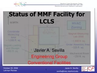
The LCLS Laser-HeaterP. Emma, forThe LCLS Commissioning TeamLBNL µ-BI MeetingOct. 7, 2008 • Layout and Design • Status of Installation • Commissioning Issues • Experiments? LCLS
LCLS Injector Layout Laser-Heater 6 MeV OTR screens (7) YAG screens (7) Wire scanners (7) RF Gun Commissioned in ‘07 Dipole magnets (8) Solenoid Beam stoppers (2) S-band RF acc. sections (5) L0a Gun Spectrometer L0b Emittance Screens/Wires Emittance Screen/Wires RF Deflector L1S 2-km point in 3-km SLAC linac X-band RF acc. section BC1 135-MeV Spectrometer TD11 stopper 135 MeV 250 MeV
LCLS Slice Energy Spread Tolerance FEL limit ~40 keV at 1 nC operating point Z. Huang et al., http://prst-ab.aps.org/abstract/PRSTAB/v7/i7/e074401
The LCLS Laser Heater (135 MeV) suggested by Saldin et al.
Laser Heater Simulations Z. Huang et al., FEL’04 Example of longitudinal phase space at 14 GeV with 8% initial modulation at 150-µm modulation
Layout of the Laser Heater Optical System in the Laser Lab Adjustment of the telescope changes the beam size in the heater-undulator Waveplate & polarizer PC & polarizer Pulse Stretcher 3 lens Telescope Shutter PH1 PH2 To streak camera Energy control UV beam UV Conversion Unit to vertical transport tube IR Laser System Path Length Adjuster Sasha Gilevich
Layout of the Laser Heater Optical System in the Injector Vault 758 nm transport to the tunnel OTR screens e- MH4 vacuum transport to LH shutter VHC camera wave plate photodiode MH4, MH3, MH2 - Motorized mirrors MH2 & MH3 are closed-loop control Waveplate and polarizer in front of both cameras MH3 MH2 power meter CH1 camera Sasha Gilevich
Injector Vault (Oct. ’07) transverse RF deflector 6-135 MeV booster linac RF gun (+ Dave) OTR screens & wire-scanners
Laser Heater Table in the Vault MH3 VHC on motorized XY stage CH1 WP VHC To powermeter WP CH1 MH2
Laser Heater Table in the Vault From MH2 Waveplate To VHC 50% beamsplitter MH1
IR Beam at Center of “Undulator” ~Sep. 30, 2008
Laser Heater Controls Panel Matt Boyes
Damping of COTR? (1 nC, 40 keV rms heating) • BC1: • COTR suppression for: 2psE/E0R56 >> l • 2p(40 keV)/(250 MeV)(39 mm) = 39 µm >> 1 µm • BC2: • COTR suppression for: 2psE/E0C1R56 >> l • 2p(40 keV)/(4.3 GeV)4.5(25 mm) = 7 µm >> 1 µm similar numbers at 250 pC with sE = 20 keV
Laser-Heater RF Gun OTR screens (7) Solenoid YAG screens (7) Wire scanners (7) L0a Dipole magnets (8) Beam stoppers (2) Gun Spectrometer L0b S-band RF acc. sections (5) Emittance Screens/Wires Emittance Screen/Wires RF Deflector L1S 2-km point in 3-km SLAC linac X-band RF acc. section BC1 135-MeV Spectrometer TD11 stopper 135 MeV 250 MeV RF Deflector (LOLA) + special lattice configuration in spectrometer allows fine measurement of time-sliced energy spread (to <6 keV) sE 6 keV rms (40 mm)
Laser Heater Commissioning Schedule • All laser-heater systems will be ready by Nov. 3, 2008, except the LH-undulator (magnet vendor was late) • LH-undulator will be installed in Dec. or Jan. • FEL begins commissioning in March (must have LH ready) • Ideas for reasonably well thought out experiments are welcome laser heater commissioning There is not limitless time available. Pressures to establish FEL arise quickly after March 15, 2009.
LCLS Commissioning StatusP. Emma, forThe LCLS Commissioning TeamLCLS SAC MeetingOctober 20, 2008 • Machine Performance • Estimated FEL Power • Present Stability • Ultra-Short Pulse Possibilities LCLS
Injector (35º) at 2-km point Existing 1/3 Linac (1 km) (with modifications) New e- Transfer Line (340 m) X-ray Transport Line (200 m) Undulator (130 m) Near Experiment Hall Far Experiment Hall Linac Coherent Light Source at SLAC X-FEL based on last 1-km of existing linac 1.5-15 Å
beam parked here Nov 2008… Commission Jan-Aug 2008 Commission Mar-Aug 2007 LCLS Accelerator Layout 250 MeV z 0.19 mm 1.6 % 4.30 GeV z 0.022 mm 0.71 % 13.6 GeV z 0.022 mm 0.01 % 6 MeV z 0.83 mm 0.05 % 135 MeV z 0.83 mm 0.10 % Linac-X L =0.6 m rf= -160 Linac-0 L =6 m rf gun L0-a,b Linac-3 L 550 m rf 0° Linac-1 L 9 m rf -25° Linac-2 L 330 m rf -41° 25-1a 30-8c 21-3b 24-6d ...existing linac 21-1 b,c,d undulator L =130 m X BC1 L 6 m R56 -39 mm BC2 L 22 m R56 -25 mm undulator DL1 L 12 m R56 0 DL2 L =275 m R56 0 SLAC linac tunnel research yard X-rays in spring 2009
Phase-II Commissioning Highlights (2008) • Injector Commissioning: Apr-Aug, 2007 (DONE) • Phase-II Commissioning: Dec-Aug, 2008 (DONE) • Great drive-laser uptime (99%) and good performance • Projected emittances 0.7-1.6 mm at 0.25 nC, 10 GeV • Routine 30-Hz e- to 14 GeV (~24/7 with ~90% up-time) • Bunch compression fully demonstrated down to 1-2 µm • Many beam & RF feedback systems running well • Electron bunch appears bright enough to drive 1.5-Å FEL • 20-pC bunch with 0.14-µm emittance (& ~10 fs length?)
Laser Spatial and Temporal Shaping in 2008 2008 6.6 ps 2R = 1.4 mm 2008 99% Drive Laser up time! S. Gilevich, G. Hays, P. Hering, A. Miahnahri, W. White Temporal shape (6.6 ps FWHM) Spatial shape on cathode using iris
Projected Emittance <1.2 μm at 1 nC (135 MeV) OTR screen gex = 1.07 μm meets injector goals 95% area cut Gaussian overlay not used gey = 1.11 μm
BC2 (4.3 GeV) TCAV (5.0 GeV) BSY (14 GeV) 550 m Bunch Compression & CSR Measured after BC2 (0.25 nC) sz < 5 mm nominal sz 2 mm old screen used sz > 25 mm L2 4 wires
Laser & Electron-Based Feedback Systems • Transverse Loops Stabilize: • Laser spot on cathode • Gun launch angle • Injector trajectory • X-band cavity position • Linac trajectory (2) • Undulator traj. (future) • Longitudinal Loops Stabilize: • DL1 energy • BC1 energy • BC1 bunch length • BC2 energy • BC2 bunch length • Final energy Laser BPMs CER detectors Steering Loop sz1 sz2 V0 d0 gun d3 d1 d2 L0 1 2 V1 V2 V3 L2 L3 X L1 D. Fairley, J. Wu DL2 DL1 BC1 BC2
bunch charge DQ21/2/Q = 1.5% Bunch Length & Energy Feedback Systems DL1 energy BC1 energy 0.03% rms 0.05% rms Final e- energy BC2 energy CSR-based bunch length monitor 0.03% rms 0.09% rms Charge feedback: Q = 0.25 nC 216 ± 12 A 2170 ± 217 A BC1 peak current BC2 peak current
Normalized phase space centroid jitter after BC1 (~4% of rms beam size) RMS AyN = 3.4% RMS AxN = 3.9% Stability is not so far from our goal (~10%) 1-s beam size D. Ratner … near end of linac (10-15% of rms beam size) RMS AyN = 9% RMS AxN = 14% Thanks to Controls group for new BPM electronics! DE/E jitter 0.03% DQ/Q jitter 1.5% Q = 0.25 nC
Measuring Bunch Arrival Time Jitter BPM Y Position (mm) TCAV OFF TCAV ON 9 mm rms 110 mm rms Dt±0.6 ps e- S-band (2856 MHz) BPM V(t) Q = 0.25 nC slope = -2.34 mm/deg Now measure BPM jitter both with transverse RF OFF, and then ON (at constant phase) Timing Jitter (w.r.t. RF) = (110 mm)/(2.34 mm/deg) = 0.047 deg 46 fsec rms
Emittance Near End of Linac Over Long Weekend g(exey)1/2 = 1.04 mm (3.3 days) May 24, 2008 00:01 to May 27 09:00 long weekend run at 0.25 nC with no tuning
Beam Appears Bright Enough for FEL Saturation at 0.15 nm M. Xie method, with wakes FEL Power 3D Gain Length Calculation based on measured end-of-linac projected emittance values, measured peak current, and design undulator parameters (assuming undulator alignment and 0.01% rms slice energy spread – not yet measurable)
Time-sliced x-Emittance at Very Low Charge TAIL 0.14 µm (not same data) 20 pC, 135 MeV, 0.6-mm spot diameter, 400 µm rms bunch length (5 A) Also measured at 0.6 µm at 250 pC & 1.2-mm laser spot diameter (40 A)