Download
1 / 24
240 likes | 462 Views
ANALOG BACK-ENDS OF GMRT. Sandeep C. Chaudhari GMRT Observatory, Khodad. ANALOG RECEIVER SYSTEMS. Feed & Front End System. Local Oscillator System. Intermediate Frequency System. Fiber optics System. Baseband System. GMRT RECEIVER SYSTEM SIMPLIFIED.

E N D
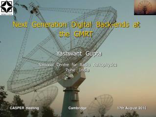
ANALOG BACK-ENDS OFGMRT Sandeep C. Chaudhari GMRT Observatory, Khodad
ANALOG RECEIVER SYSTEMS • Feed & Front End System. • Local Oscillator System. • Intermediate Frequency System. • Fiber optics System. • Baseband System.
GMRT RECEIVER SYSTEM SIMPLIFIED • Frequencies of operations 150, 233, 327, 610, 1420 MHz. • IF bandwidth variable – 6, 16, 32 MHz. • Coherent Local Oscillator phase locked to a Master time & frequency. • IF signals brought to central building using optical fiber links. • Baseband system adds more selectable bandwidths. • Correlator system multiplies the signals and integrates over long time interval.
LOCAL OSCILLATOR SYSTEM • What is the need of LO system at GMRT? • Conversion of RF signals to an Intermediate Frequency for onward transmission to CEB. • System Description :- • LO Reference Master (LORM) system at CEB. • LO Reference Remote (LORR) system at ABR. • LO Synthesizer (LOS) system at ABR. • System Features :- • High stability and low Phase noise Reference 5MHz primary ref. for GMRT LO freq. std. • Phase coherent and low phase noise secondary reference for :- • Cater need of ref. for LO synthesizer. • II LO requirement for freq. translation in IFS at ABR. • III LO requirement in BB for freq. re-translation. • Reference requirement for IV LO synthesizer in BB. • Facility to generate two different LO frequencies for Dual Frequency observations.
Local Oscillator System • Why Phase coherent Local oscillator signals are required? • To maintain relative phases between the signals from different antennas. • The phase of the RF signal received at the feed is maintained as the signal flows through the receiver chain. • Why Round Trip Phase Measured? • Effect of different locations of antennas and length of fiber on phase of the transmission frequency band. • Estimates Phase behaviors of fiber over the transmitted signal. • Achieved by bringing back 2nd LO to CEB and comparing it's phase with that of signal originally generated at CEB.
SPECIFICATIONS OF LO SYSTEM • LOM specs :- • Frequency and Time standard : Rubidium Crystal Oscillator • Output Freq. : 10MHz. • Time Accuracy : +/- 25 ns. • SSB Phase noise : -85 dBc/Hz at 1Hz offset. • Harmonics : -50 dBc. • First LO synthesizer :- • Frequency Coverage : 100MHz to 1600MHz. • Step Size : 1 MHz from 100MHz to 400MHz : 5MHz from 400 to 1700MHz. • Power output : +11dBm to +3dBm. • Harmonics : Better than -20dBc. • Phase noise : Better than -60dBc/Hz at 10KHz offset. • Second and Third LO source and offset frequency sources • Oscillator circuit : Transistorized VCXO operating in a PLL. • Spurious : Better than -50dBc. • Harmonic : Better than -70dBc. • SSB Phase noise : Better than -90dBc/Hz at 100Hz offset.
IF SYSTEM • Functions :- • Common signal processing & conditioning irrespective of input RF band. • Provide better Image frequency Rejection & Better dynamic range in the intermediate stage. • Frequency Upconversion. • Gain Loss Compensation in receiver chain. • Bandwidth selection options as observation requirement.
IF SYSTEM BLOCK DIAGRAM Filter Bank Ist Mixer & Amp Filter Bank Ist Mixer & Amp ALC
IF SYSTEM SPECIFICATIONS • Output IF signal CFs : 130MHz and 175 MHz. • O/p signal BW selection : 6MHz, 16MHz, 32MHz. • Pre-attn adjustment range : 0 to 30 dB in steps of 2dB. • Post Gain adjustment range : -2.5 to +32.5dB in 0.5dB step. • IF ALC switch : On/ Off. • Dynamic range • ALC ON : 28 dB. • ALC OFF : 32 dB. • Output 1 dB compression point : +15dBm. • Output IMD : 55 dBc. • ALC Time constant : • Trise = 220 ms@5dB step size and @PBase = -35dBm. • Tfall = 950ms@5dB step size and @PBase = -35dBm.
IF SYSTEM ALC/VGA CHARACTERISTICS • VGA characteristics, • G = 12 dB. (Red) • G = 4 dB. (Pink) • ALC Characteristics (Blue).
IF SYSTEM SPECTRUMS Bandwidth Selection From C41 Output spectrum of ABR
BASE BAND SYSTEM • Functions of Baseband System :- • Converts IF signals to lower frequencies suitable for sampler in correlator. • Provides facility to vary the observation signal bandwidth over a wide range. • Provides level control circuits to keep the power fed to sampler within acceptable range irrespective of gain variation in the OF and baseband electronics.
BASE BAND SYSTEM BLOCK DIAGRAM Base Band Mixer
BASE BAND SYSTEM SPECIFICATIONS • Baseband Signal Characteristics :- • Baseband Frequency Range : 10 KHz to 16 MHz. • Baseband Signal Power Level : 0 dBm +/- 0.4 dBm. • Baseband Image Rejection : > 25 dB. • Passband Ripple : < 0.5 dB. • Stop band Attenuation : > 40 dB. • Inter-modulation Distortion : < -35 dB. • ALC Time Constant : 1.0 sec ( ALC response ). • Baseband Control Settings :- • BB Filter BW Selections : 62, 125, 250, 500 KHz, 1, 2, 4, 8,16 MHz. • BW Compensation Gain Sel. : 0 to 24 in 0.5 dB steps. • IV LO Characteristics :- • Tunable Frequency Range : 50-90Mhz, 100Hz Step. • Spurious Signal Levels : <-60dBc Non-harmonic, <-30dBc Harmonic • Phase Noise : < -80 dBc/Hz at 100 Hz.
SSB MIXER IN BASEBAND SYSTEM • Why SSB Mixer? • Baseband Freq. Conversion aspect. • Image Freq. Rejection concept in terms of GMRT signal.
UPGRADATION PLANS • Broad Band Feed Development. • Broad Band LNA Development. • Optical Fiber Development - Bringing Direct RF to CEB. • Direct Digitisation and Down Conversion of RF signals – Band Pass Sampling concept. • Software based Correlator Development.
REFERENCES, FURTHER READINGSAND CONTACTS • Low Frequency Radio Astronomy, Chengalur, J. N, Y., Gupta, Dwarkanath, K. S. • GMRT Local oscillator Reference system Reference manual, R., Somshekhar. • Information on Base-Band System www.gmrt.ncra.tifr.res.in/gmrt_hpage/sub_system/baseband/bb.html • Contact Persons :- • IF & LO System :– Shri. T.L. Venkatsubramani, Shri. Navnath Shinde. Shri. Sudhir Phakatkar • BASE BAND :- Shri. Ajith Kumar, Shri. P. J. Hande.