Download
1 / 28
280 likes | 292 Views
Measurements of Laser Induced Ionizing Radiation Doses at SLAC. SLAC RP: Johannes Bauer, James Liu, Sayed Rokni, Henry Tran, Maranda Cimeno, Mike Woods. SLAC LCLS:

E N D
Measurements of Laser Induced Ionizing Radiation Doses at SLAC SLAC RP: Johannes Bauer, James Liu, Sayed Rokni, Henry Tran, Maranda Cimeno, Mike Woods SLAC LCLS: Bob Nagler, Eric Galtier, Eduardo Granados, Hae Ja Lee, Phil Heimann, Dan Peterswright, Oscar Guerra, Ruben Curiel, Alex Wallace, Perry Anthony, Alyssa Prinz Ted Liang Georgia Tech/SLAC Anna Ferrari Helmholtz-Zentrum Dresden SATIF 12, April 28-30, 2014, FNAL, IL, USA
Outline • Introduction • LCLS MEC Instrument • Ionizing Radiation Production • Source term • SLAC Measurements • Set-up, parameters, issues • Results • Comparison with RP models and FLUKA results • Summary
LCLS MEC Layout The Matter in Extreme Conditions (MEC) instrument combines the unique LCLS FEL beam with high power optical laser beams to study the transient behavior of matter in extreme conditions. MEC serves key scientific areas including Warm Dense Matter physics, High Pressure studies, shock physics, and High Energy Density physics.
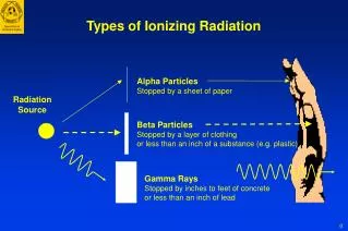
Ionizing Radiation in Laser-Target Interactions Target Plasma H.A. Baldis, E.M. Campbell, W.L. Kruer. “Handbook of Plasma Physics,(1991). Laser e- e- hadrons X ray
Electron Spectrum and Effective Temperature 50mm Ag target Hui Chen et al., LLNL-PRES-416551 (2009) and Physics of Plasmas 16, 020705 (2009) The generated electron spectrum and effective temperature (Th) are sensitive to Ilaser (W/cm2), but not sensitive to the Z of target material.
Electron Angular Distribution Y. Ping et al., Phys. Rev. Lett. 100, 085004 (2008). • At lower intensity, most of the hot electrons are emitted at the target front side. • At middle intensity, the back side component increases to become comparable • with the front side part, and there is a distinct peak in the laser direction. • At higher intensity, hot electrons at the back side are dominant, with peaks in the • laser direction and target normal.
Maximum Photon Dose Y. Hayashi , A. Fukumi et al. Radiat Prot Dosimetry 121 (2): 99-107 (2006) Pef - laser energy to electron energy conversion efficiency, R - distance from the target to measurement point in cm, and T - hot electron temperature in MeV.
MEC Measurements 2012: 3.0x10¹⁶ to 6x10¹⁷ W/cm2 • (100 m & 10 m Au, 1 mm Cu) • 2014: • 2x10¹⁸ W/cm2 • (100 m Cu) • 2x10¹⁹ W/cm2
images from Landauer Al2O3 Landauer nanoDot OSLD • Single chip radiation dosimeter • Energy range from 5 keV to 20 MeV • Linear response up to 300 cGy
SLAC MEC Laser: Target Rastering • Gold foils after use • thick and thin foils
SLAC MEC Feb. 2014 Experiment • Laser: • Energy entering chamber = 950 mJ (±6%) • Pulse length = 70 fs (±5) • Laser power = 14 TW (±13%) • Repetition rate = 1 Hz • Optic: • FWHM of peak = 15x9 μm2 • Energy in peak = 200 mJ • Intensity of peak = 1.8x10¹⁸ W/cm2 (±15%) • Target: • Total shots on 100-μm Cu target = 540 Irradiance (W/m2) Spot size (m)
SLAC MEC Laser: 6x10¹⁷ W/cm2, 10 Hz • PTW ion chamber HPI 6032 ion chamber PTW PTW SLAC HPI-6032 HPI-6031 HPI 6031 “soup cup” (couresy of LBNL) HPI-6031
SLAC MEC Laser: 6x10¹⁷ W/cm2, 10 Hz, outside Hutch 1 mm Cu 100m Au
SLAC MEC Laser: Mirror Damage Damage to Off-Axis-Parabolic Mirror after Kapton and Gold shots Before After Mitigation is not using Kapton, moving mirror farther away
SLAC MEC Feb. 2014: Integrated Dose inside Target Chamber BF3 Station HPI-6031 Dose (cGy) Vic-451 3.9 Laser Intensity: I = 1.8x10¹⁸ W/cm2 Target: 100 μm thick Cu Laser: 540 shots 108 J total Vic-451 11.2 1.6 66.6 5.7 147.4 0.001 122.5 15.6 12.5 BF3 Station 0.018 4.5 99.3 0.6 HPI-6031 0.5 0.2
SLAC MEC Feb. 2014: Dose at 30 cm inside Target Chamber Y. Ping et al., Phys. Rev. Lett. 100, 085004 (2008). Dose (cGy) FEL axis Dose (cGy) • Laser at 15o • off target normal Targets: Al foils (1.5-100 μm) Si plate (400 μm) Laser of intensity 1.8x10¹⁸ W/cm2 incident on 100-μm Cu target at chamber center
H*(10) Dose Map from FLUKA Local shielding 12 cm steel Copper target 100 μm thick I=1.8x10¹⁸ W/cm2, Monodirectional Electron Source
H*(10) Dose along Laser Axis Local shielding 12 cm steel MEC Aluminum chamber wall I=1.8x10¹⁸ W/cm2 Monodirectional Electron Source
FLUKA H*(10) Dose Map Isotropic Source Term Monodirectional Source Term I=1.8x10¹⁸ W/cm2 Th=183 keV 100-μm Cu target
Summary • Experiments have been performed at SLAC MEC with a high intensity laser focused on solid targets; Th ranging from 20 keV (3x10¹⁶ W/cm2) to 180 keV (2x10¹⁸ W/cm2) • Measurements show photon doses outside target chamber starting at 3 x10¹⁶ W/cm2 • Neutron doses of 3x10⁻⁸ mSv/J (~1 μSv/h at 10 Hz, 150 mJ) was measured starting at 6x10¹⁷ W/cm2 (neutron-to-photon dose ratio of 0.1%) • Analytical model overestimates the measurements at very high intensities >1020 W/cm2 and underestimate <1018 W/cm2 • Measurements of photon H*(10) outside the target chamber agree with FLUKA results • Analysis of results from electrons inside the chamber are ongoing; also using Particle-in-Cell (PIC) Plasma Code to study angular and energy distributions • Plans are underway for measurements at higher laser intensities; up to 2.0x10²⁰ W/cm2 (Th=3.5 MeV)
Measured Dose Summary • Outside Target Chamber • Dose due to Bremsstrahlung photons: • Maximum measured photon dose rate = 60 μSv/h • Maximum integrated dose from passive dosimeters = 6 μSv • Dose due to neutrons: • Maximum neutron dose rate = 30 nSv/h • Neutron to photon dose fraction = ~10-3 • Inside Target Chamber • High dose up to 150 cGy inside chamber due to low energy e– and photons: • Majority attenuated by Al chamber walls • Majority of dose directed in backwards direction of target
Measurements of Laser-Induced Radiation Dose Yield at 1m Existing Measurements (compilation by Bob Nagler, SLAC, R. Clarke RAL)