Download
1 / 16
160 likes | 305 Views
CIM with PDX installation. Martin Marietta. Monday April 12 th , AM/PM - Bud, Michael. I stopped at the Home Depot on the way to MM for the J-Boxes and cable connectors. When I got there we started by replacing the large 6 conductor cable with a small 5 conductor cable for the wheel detectors.

E N D
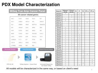
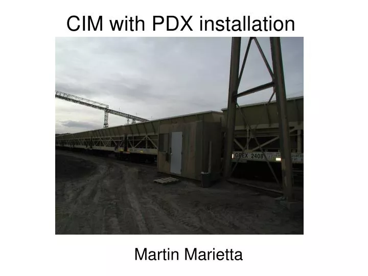
CIM with PDX installation Martin Marietta
Monday April 12th, AM/PM - Bud, Michael • I stopped at the Home Depot on the way to MM for the J-Boxes and cable connectors. • When I got there we started by replacing the large 6 conductor cable with a small 5 conductor cable for the wheel detectors. • We did this just to make some room in the conduit for other cables that will be necessary. • Next we wired 3 pit junction boxes for the wheel detectors (1) and RFID readers (2). • You now know the necessity of a couple of two inch diameter conduits between the scale and the controller. • This would have eliminated the need for any j-boxes. (there should be NO J-BOXES in the pit) • With future installations we must make sure there is enough conduit capacity so no wires need be cut between the scale and the controller. • Once the pit j-box wiring was complete we tested the individual wheel detectors. I did notice that W/D 3 did not increment its’ count like 0,1, and 2 did. I confirmed here that this is a bug in the application software and the count is correct when the CIM application is in operation. This just hampers testing a bit. • The PDX load cells were wired to the IND780. There was a ground wire missing, so I just attached the shield to the IND780 enclosure. (this needs to be fixed, see next slide) • Cell addressing and raw counts looked fine. No changes required. • I updated the IND780 firmware and restored a memory backup from the USB stick. • The CIM continuous data looked stable and the filter response was as expected. • I also replaced the 24V 1A supply in the IND9R86 with the 24V 2A supply from the 3rd RFID junction box. (print and BOM need to be updated)
Monday April 12th, PM – Bud, Stephan • Stephan wired the RFID reader connections at both pole mounted j-boxes. • (the RFID j-boxes in the pit just connect the cut 6 conductor wires) • Bud connected all the RFID wires inside the controller. We next tested the RFID COM using HyperTerminal on COM2 (far side reader) and COM4 (near side reader) • Once COM was working Bud programmed the readers with the following commands: • Far side - #01 #66F #453 #300 #311 #4102 • after programming the status command #527 returns • #RFST C0 O1 T1 F1A R1F G1F A00 I04 • Near Side - #01 #66F #453 #300 #311 #4102 #642 • after programming the status command #527 returns • #RFST C0 O1 T1 F22 R1F G1F A00 I04 • The far side is programmed with the default operating frequency and the near side is set 919MHZ • Once the tag readers were tested we left the site for the day. (6:30pm)
Scale, Wheel Detectors, RFID Looking West toward Load Out
Tuesday April 13th, AM – Bud, Stephan • The next morning (April 13th) Stephan and I arrived at MM at 7:45am. We waited for a train so a rough calibration and shift adjust could be performed. • The wind was blowing at 40 – 50 mph and there was choking dust and dirt flying everywhere. • The train did come at about 11:00am and we did complete the rough calibration and shift adjustment. • I wanted the operator to pass the train over the scale in both directions, but he indicated there were other trains entering soon so it was not possible. • Once that train was gone I made an adjustment to the wheel detector locations based on what I saw on the previous train pass. • We drove to Cheyenne and ate lunch. • When we returned to the site we waited for a train. • The 60 car empty train showed up around 1:15pm • When it began its’ pass over the scale I noticed WD1 was oscillating. • So, I had to wait 4 hours while this train loaded to re-position WD1.
Tuesday April 13th, PM – Bud, Stephan 60 car empty train loading, nothing to do but wait………
Wednesday April 14th, AM/PM – Bud, Stephan • We arrived at the site at 8:00am and saw the trains had not moved from the previous day. • So, we went to the quarry office to speak to Pete Bovis the MM Administrative Services Supervisor. We discussed the testing so far and asked about the availability of a test train. He indicated one may be available on Thursday. • We then drove to Cheyenne and headed North to Wright, WY to visit potential customers in the Powder River Basin. (250 miles North) • We visited Thunder Basin Coal Company and discussed CIM scale application there with Paul Barber and Jay Wilkerson. • At that mine we looked at 7 different CIM scales provided by our competitor. (SAI) • The visit gave me valuable insight to CIM scale operations at coal load outs. • We returned to Cheyenne late Wednesday.
Thursday April 15th, Bud • Arrived at the MM site at 8:20am and stored the data that was collected from the previous day. • I discussed the need for a test train with Pete Bovis via cell phone and he indicated there would be a small train on site for use in scale testing. • So, I re-measured the wheel detector and bracket locations. From my calculations the two sets of brackets needed to be move closer to the center of the scale (87” center to center vs. 90”) I had no tools so I improvised with a pipe, hammering the East wheel detector bracket toward the center by 2.5”. • So now the distance between the East and West side wheel detectors to the edge of the scale is 29”. I also used a 10mm spacer to set the W/Ds distance to the rail. • I waited a while and the yard operator stopped by the scale. He told me that the small train would be loading soon. I asked if he could have it pass the scale a few times to test the CIM controller. He indicated that there would be additional traffic and he could not. I asked him to contact Pete to confirm what I was requesting was authorized. He drove away and the small train began backing over the scale. It stopped when the Engine reached the load out. • From that pass I was able to see that W/D 3 had a few random oscillations. • Once the 20 car train passed the scale I replaced WD3. • So, with no engine passing over the scale I could not verify the proper location of wheel detectors (East/West spacing) for the engines that are used. (6 axle 84” spacing) • I left the site for lunch at 1:00pm
Thursday April 15th, PM - Bud • Before leaving the site I called Pete, but only got voice mail. • While in Cheyenne I called Michael and discussed the situation. • There were some phone calls, but there was no one available that knew about the loading schedule. • So, it was decided that the system would continue to log data and Michael or Tom could stop at the site at a later date to collect the logged data. • That data could be sent to me to analyze. • Yes, I was pretty disappointed that I could not test the system to my satisfaction. • The final spacing for the wheel detectors is shown below
Recommendations • 1. The ground rod should be planted near the power drop from the overhead conveyer. • 2. The ground strap should be run from the ground rod to the StrikeShield. • 3. The IND780 home run cable should be properly grounded as shown in the install manual. • 4. The electronics hut must be climate controlled with A/C and heater. • 5. The scale pit must have an automatic sump pump installed. • 6. The RFID tag readers on the near side must be set to 42” above the rail. • 7. The far side RFID reader must be ground mounted to improve safety. (pole cut down) • 8. The scale calibration scheduled. • 9. The South East rail cut must be increased. (binding now) • 10. There must be holes drilled in the scale deck to route the W/D cables. (with strain relief) • 11. It would be a big help if there was a window on the North side of the scale shack so the scale is visible from inside the shack. • 12. There is a lot of junk piled inside the shack that should be removed. • 13. There needs to be a dust filter added to the UPS since it has an exhaust fan. • 14. The power for the CIM controller needs to be powered by the UPS. (remove conduit between service box and the controller. (wire directly from UPS to the IND9R86) • 15. Traffic light should be added for scale status and speed indication. • 16. Ethernet should be connected to scale shack for CIM data. • 17. Dust control!!!!
Martin Marietta Pictures UPS Strike Shield IND9R86
Martin Marietta Pictures South East Rail Cut