Download
1 / 52
520 likes | 678 Views
MULTI-STAGE COLLECTOR (MSC™) DEVELOPMENT. Introduction. Multi-Stage Collector The MSC™ offers a new method and design for collecting dust or fume from industrial gases that is virtually independent of electrical resistivity

E N D
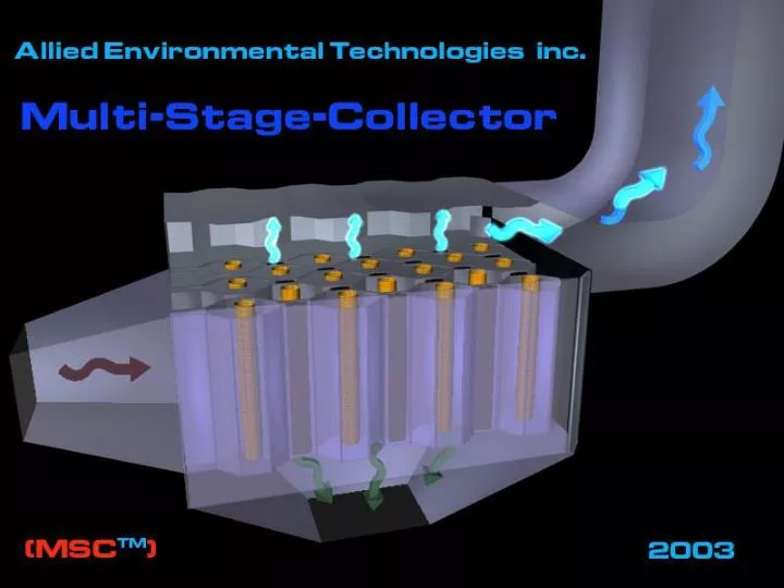
MULTI-STAGE COLLECTOR (MSC™)DEVELOPMENT Allied Environmental Technologies, Inc. - MSC™ Development
Introduction Multi-Stage Collector • The MSC™ offers a new method and design for collecting dust or fume from industrial gases that is virtually independent of electrical resistivity • This design will be particularly advantages when the material to be collected consists of a sub-micron dust or fume Allied Environmental Technologies, Inc. - MSC™ Development
Evolution of Electrostatic Precipitation Allied Environmental Technologies, Inc. - MSC™ Development
Evolution of Electrostatic Precipitation • A typical electrostatic precipitator incorporates two zones: • the CHARGING zone, where the dust or aerosol particles are being charged, and • the COLLECTING zone, where the charged particles are being separated and transferred from the gas stream to a collecting electrode Allied Environmental Technologies, Inc. - MSC™ Development
Evolution of Electrostatic Precipitation • The arrangement of these zones led to two typical precipitator design concepts: • an electrostatic precipitator where both zones are combined in a Single-Stage, and • a Two-Stage design where these zones are separated Allied Environmental Technologies, Inc. - MSC™ Development
Evolution of Electrostatic Precipitation Two-Stage Precipitator Single-Stage Precipitator Allied Environmental Technologies, Inc. - MSC™ Development
Evolution of Electrostatic Precipitation • Here is different design for a Two-Stage ESP • It utilizes the unique electrode design that provides for separate zones for aerosol particles charging and collection in a compact design • According to this design, the dust collecting assembly comprises of a system of bi-polar charged surfaces, which are engineered in such a way that they provide alternate separate zones for high-tension non-uniform and uniform electrostatic fields The spacing between the surfaces in the charging and collecting zones is different, wider in the charging or corona generating zones and narrow in the collecting ones where a uniform high-tension electric field is being required Allied Environmental Technologies, Inc. - MSC™ Development
Barrier Filtration Allied Environmental Technologies, Inc. - MSC™ Development
Barrier Filtration • Fabric filters are a popular means of separating particles from a gas stream because of their relatively high efficiency and applicability to many situations • Fabric filters can be made of either woven or felted fabrics and may be in the form of sheets, cartridges, or bags, with a number of the individual fabric filter units housed together in a group • Bags are by far the most common type of fabric filters, hence the use of the term "baghouses" to describe fabric filters in general Allied Environmental Technologies, Inc. - MSC™ Development
Barrier Filtration • Ceramic filters have become available that can be used for high temperature filtration applications • Ceramic material is formed into stiff cylindrical filter elements, called "candles" • The open ends of the tubes are mounted either vertically or horizontally on a tubesheet, as with fabric bags • Tubes are generally cleaned by pulse jets • During the last years, porous metal media had gained importance in the field of gas dedusting or product recuperation in gas streams • The two most widely used types of porous metal media are sintered metal fiber and sintered metal powder Allied Environmental Technologies, Inc. - MSC™ Development
Barrier Filtration • The major particle collection mechanisms of fabric filters are inertial impaction, diffusion from Brownian motion, and interception • Collection may also occur due to gravitational sedimentation • Electrostatic attraction could play a significant part, for example in the Electrostatically Augmented or Enhanced and Hybrid technologies • The fabric is responsible for some filtration, but more significantly it acts as support for the dust layer • The layer of dust, also known as a filter cake, is a highly efficient filter, even for submicron particles Allied Environmental Technologies, Inc. - MSC™ Development
Barrier Filtration Particle Collection Mechanisms in Barrier Filters EPA- 450/3-81-005a, NTIS PB83-127498 Allied Environmental Technologies, Inc. - MSC™ Development
Hybrid Particulate Collection Technology Allied Environmental Technologies, Inc. - MSC™ Development
Hybrid Particulate Control Technology • Electrically-charged particles have been found to form highly porous dust layers in fabric filters • Efforts to increase barrier filters efficiency without a corresponding increase in pressure loss have led to the development of electrostatically enhanced fabric filters and so-called hybrid devices Allied Environmental Technologies, Inc. - MSC™ Development
Hybrid Particulate Control Technology • A combination fabric filter/ESP hybrid device has been developed by EPRI and is called the Compact Hybrid Particulate Collector (COHPAC): • This device involves using pulse jet fabric filtration to capture dust that escapes an ESP • COHPAC I involves placing a pulse jet filter downstream from an ESP • COHPAC II utilizes a fabric filter in place of the last field(s) of an ESP Allied Environmental Technologies, Inc. - MSC™ Development
Hybrid Particulate Control Technology • Advanced Hybrid • This technology was developed and patented by the University of North Dakota’s Energy & Environmental Research Center (EERC) • The internal geometry consists of alternating rows of ESP components (discharge electrodes and collecting plates) and filter bags within the collector • The inlet flue gas is directed into the ESP zone, which removes most of the entrained dust prior to it reaching the filter bags Allied Environmental Technologies, Inc. - MSC™ Development
Hybrid Particulate Control Technology • ESFF • Electrostatically-stimulated fabric filters (ESFF) have been developed by EPA to reduce fabric filter pressure drop and particle penetration Allied Environmental Technologies, Inc. - MSC™ Development
Multi-Stage Collector(MSC™) Allied Environmental Technologies, Inc. - MSC™ Development
Multi-Stage Collector - MSC™ • The principal objective of the MSC™ design is to substantially improve fine particulate collection by: • combining electrostatic charging - collection and filtration processes, while • separating zones for particles charging and collecting Allied Environmental Technologies, Inc. - MSC™ Development
Multi-Stage Collector - MSC™ • The MSC™ concept can be broadly summarized as a system in which multiple stages are utilized, with each stage performing a primary function and multiple stages operating synergistically to provide significantly improved overall results Allied Environmental Technologies, Inc. - MSC™ Development
Multi-Stage Collector - MSC™ • The MSC™ offers a uniquely compact concept utilizing: • an upstream stage comprised of a conventional ESP, • followed by a downstream zone of the parallel surfaces creating uniform electric field, • followed by yet another stage, which incorporates barrier filter, surfaces of which provide yet additional zone with uniform electric field • Moreover, by providing continuously repeated stages in series, the downstream zones effectively re-charge and re-collect the particles that are either uncollected or reentrained and collect those particles after they have been charged Allied Environmental Technologies, Inc. - MSC™ Development
Multi-Stage Collector Stage-2 (Uniform Filed): Precipitation Stage-2 (Uniform Filed): Precipitation Stage-3 (Barrier Filter): Filtration + - + - + - Stage-1 (Non-Uniform Field): Charging + - + Allied Environmental Technologies, Inc. - MSC™ Development
Multi-Stage Collector Stage-3 (Barrier Filter): Filtration Stage-2 (Uniform Filed): Precipitation Stage-2 (Uniform Filed): Precipitation Stage-1 (Non-Uniform Field): Charging Allied Environmental Technologies, Inc. - MSC™ Development
Multi-Stage Collector - MSC™ • The MSC™ assembly is made up from DE’s placed between oppositely charged corrugated plates • The DE’s are followed by BFE’s located in wide zones placed between the collecting electrodes • The corrugated plates are held at a first electrical potential while the DE’s and the BFE’s are held at a second electrical potential Both the flat sides of each of the DE’s, corrugated plates and the surfaces of the BFE form collecting surfaces where the electric field is relatively uniform Allied Environmental Technologies, Inc. - MSC™ Development
Multi-Stage Collector - MSC™ The center region of uniform field on the other hand acts in a manner similar to the field between parallel capacitor plates with charged dust particles collecting on the plates of opposite polarity The center region of uniform field on the other hand acts in a manner similar to the field between parallel capacitor plates with charged dust particles collecting on the plates + At sufficiently high field strength in this non‑uniform field region, a corona discharge can take place between the electrode and the plates acting as an ion-charging source for dust particles passing through it + - - - + + Allied Environmental Technologies, Inc. - MSC™ Development
Evolution of Electrostatic Precipitation Courtesy of Aerosol & Particulate Research Lab Allied Environmental Technologies, Inc. - MSC™ Development
Evolution of Electrostatic Precipitation Major Distinctive Points Gas Flow • The MSC™ is engineered in such a way that the BFE and the DE are grounded while the corrugated electrodes are suspended from the insulators • By virtue of having the BFE’s at the same potential as the DE’s, the MSC™ design completely eliminates any potential sparks from the DE toward the BFE, thus eradicating any chances of causing fires and/or puncturing holes in the porous barrier media • Hence, whether the MSC™ is powered by a “conventional” or an alternating power source, the BFE’s remain protected from any sparks from the DE irrespective of dust concentrations - + + - + - + Allied Environmental Technologies, Inc. - MSC™ Development
Computational Fluid Dynamics Modeling Allied Environmental Technologies, Inc. - MSC™ Development
CFD Simulation • In order to evaluate the MSC™ design, a detailed analysis of gas flow dynamics were performed with an aid of the Computational Fluid Dynamics (CFD) technique • CFD simulation was conducted for the pilot MSC™ consisting of four (4) rows of barrier filters (bags) four (4) bags each for a total of 16 bags and five (5) collecting corrugated plates Allied Environmental Technologies, Inc. - MSC™ Development
CFD Simulation 3-D View of the CFD Model Allied Environmental Technologies, Inc. - MSC™ Development
CFD Simulation • The MSC™ operation was simulated for three (3) operating conditions with the gas flows of 0.24, 0.47, and 0.69 m3/s at 149 ºC (500, 1,000, and 1,500 acfm at 300 ºF) for the filtration velocity in the range of 5 – 15 cm/s (10-30 ft/m) • The operating pressure drop supplied by the bags was assumed about 6” WC • The simulation utilized body-fitted grid approach, which allows the use of non-orthogonal grids that can accurately represent geometry of the simulated object Allied Environmental Technologies, Inc. - MSC™ Development
CFD Simulation CFD Model Computational Grid Allied Environmental Technologies, Inc. - MSC™ Development
CFD Simulation • The simulation was carried out using standard κ-ε turbulence model with the logarithmic wall functions • The turbulence intensity at the MSC™ inlet was assumed to be 5 % • Since the pressure drop inside MSC™ is small with respect to the atmospheric pressure, the equation of state of the gas used in the simulation was the one of the constant-density gas • The bags were simulated as the porous media of the constant resistance, which was adjusted to ensure predetermined pressure loss for the gas flow simulated Allied Environmental Technologies, Inc. - MSC™ Development
CFD Simulation Velocity Distribution – 500 cfm Case Allied Environmental Technologies, Inc. - MSC™ Development
CFD Simulation Velocity Distribution – 1000 cfm Case Allied Environmental Technologies, Inc. - MSC™ Development
CFD Simulation Velocity Distribution – 1,500 cfm Case Allied Environmental Technologies, Inc. - MSC™ Development
CFD Simulation 3D - Velocity Distribution 1,000 acfm 500 acfm 1,500 acfm Allied Environmental Technologies, Inc. - MSC™ Development
Applications Allied Environmental Technologies, Inc. - MSC™ Development
MSC™ Applications • One of the most important MSC™ design improvements is very high collection efficiency in a submicron (ultra-fine) region, which extends its potential use to a wide variety of the fine particulate/dust collection applications Allied Environmental Technologies, Inc. - MSC™ Development
MSC™ Applications Allied Environmental Technologies, Inc. - MSC™ Development
MSC™ Applications • Ultra clean exhaust gases: “Vision 21” • Integrated Gasification Combined Cycle (IGCC): super-clean de-dusting process (synthetic) gases • Industrial mineral processing industries: • In-process capture of the expensive product material and return to the process, i.e. metals, rock-dust, gold, etc. • Post-processing super-clean de-dusting prior to exhaust to the atmosphere • Ultra-clean air de-dusting in high-tech, medical, biological and other similar applications • Multi-pollutant applications (SOx, NOx, Hg, etc.) via integrating (or impregnating) catalyst materials within the barrier filter Allied Environmental Technologies, Inc. - MSC™ Development
Case Study Allied Environmental Technologies, Inc. - MSC™ Development
Case Study • A Case Study was conducted in order to evaluate suitability and size requirements of the MSC™ for the “conventional” ESP retrofitting • The goal of the study was to evaluate whether it would be possible to fit the required barrier filter area and the respective ESP equipment in the existing casing • 500 MW boiler-unit firing sub-bituminous coal was selected • The existing three (3) field ESP had two (2) casings, four (4) cells each with 20 gas passages on 229 mm (9”) centers • The collecting plates were 3.66 m (12’) long and 9.14 m (30’) high • This geometry resulted in a SCA of 38.87 m2/m3/s (197 ft2/kacfm) at a gas flow of 826 m3/s (1,750,000 acfm) at 149 ºC (300 ºF) Allied Environmental Technologies, Inc. - MSC™ Development
Case Study Existing ESP (½) MSC™ Retrofit (½) Flue Gas Flue Gas Cell 4 Cell 2 Cell 3 Cell 1 Field 1 • Each Cell: 20 GP @ 9” SP • 12’L x 30’H Plates • 1,750 kacfm • SCA=197 ft2/kacfm Field 2 Field 3 Allied Environmental Technologies, Inc. - MSC™ Development
Case Study Allied Environmental Technologies, Inc. - MSC™ Development
Case Study • Assuming that the MSC™ will be able to operate with the FV in the 5 - 6 cm/s (10 - 12 ft/m) range a reasonably suitable retrofit seems possible • Naturally, as the MSC™ operation is independent of the fly ash resistivity, there will be no need to evaluate the requirements for the FGC • Hence, this unit would be an ideal candidate for the “spot market” coal • The expected system performance should be within the “Vision 21” range; hence the expected outlet emissions (≤ 0.005 lb/MBtu) should satisfy requirements of any local air pollution control regulatory office Allied Environmental Technologies, Inc. - MSC™ Development
Summary & Conclusions Allied Environmental Technologies, Inc. - MSC™ Development
Summary • The MSC™ technology is a novel, compact multi-stage collector for separating dust or fume from industrial gases, which is independent of electrical resistivity • This design should be particularly advantageous when the material to be collected consists mostly of a sub-micron and ultra-fine dust or fume • The MSC™ concept offers significant improvement over conventional ESP’s and BF’s • the MSC™ design completely eliminates any potential sparks from the DE toward the BFE, thus eradicating any chances of causing fires and/or puncturing holes in the porous barrier media Allied Environmental Technologies, Inc. - MSC™ Development
Conclusions • MSC™ solves the problem of excessive fine-particle emissions with conventional de-dusting technology • MSC™ is independent of the dust/fume resistivity • It greatly reduces the problem of higher emissions from conventional fabric filters and hybrid devices in the event of partial breaking, leakage or any system malfunctioning parts, and • It solves the problem of sparking and bags damaging in the hybrid particulate collectors Allied Environmental Technologies, Inc. - MSC™ Development