Download
1 / 39
420 likes | 608 Views
Digital to Analog Converters. Tyler Smith Brent Nelson Jerry Jackson. 10/14/04. Topics Discussed. What is a DAC? Choosing a DAC Resistor String DAC Weighted Resistor DAC R-2R DAC PWM DAC associated errors Applications Conclusion. What is a DAC.

E N D
Digital to Analog Converters Tyler Smith Brent Nelson Jerry Jackson 10/14/04
Topics Discussed • What is a DAC? • Choosing a DAC • Resistor String DAC • Weighted Resistor DAC • R-2R DAC • PWM • DAC associated errors • Applications • Conclusion
What is a DAC • A digital to analog converter (DAC) is a device that converts digital numbers (binary) into an analog voltage or current output.
Choosing a DAC There are six main parameters that should be considered when choosing a DAC for a particular project. • Reference Voltage • Resolution • Linearity • Speed • Settling time • Error
Choosing a DAC Reference Voltage To a large extent the output properties of a DAC are determined by the reference voltage. Multiplier DAC – The reference voltage is constant and is set by the manufacturer. Non-Multiplier DAC – The reference voltage can be changed during operation.
Choosing a DAC Resolution The resolution is the amount of voltage rise created by increasing the LSB of the input by 1. This voltage value is a function of the number of input bits and the reference voltage value. - Increasing the number of bits results in a finer resolution - Most DACs in the 12-18 bit range
Choosing a DAC Linearity The linearity is the relationship between the output voltage and the digital signal input.
Choosing a DAC Speed Usually specified as the conversion rate or sampling rate. It is the rate at which the input register is cycled through in the DAC. • High speed DACs are defined as operating at greater than 1 millisecond per sample (1MHz). • Some state of the art 12-16 bit DAC can reach speeds of 1GHz • The conversion of the digital input signal is limited by the clock speed of the input signal and the settling time of the DAC.
Choosing a DAC Settling Time Ideally a DAC would instantaneously change its output value when the digital input would change. However, in a real DAC it takes time for the DAC to reach the actual expected output value.
Choosing a DAC Error There are multiple sources of error in computing the analog output.
Example of a DAC - AD7224 An example of a DAC would be the Analog Devices AD 7224 D/A Converter. The AD7224 is a precision 8-bit, voltage-output, digital-to-analog converter with an output amplifier. Specifications: DAC Type – R-2R Voltage Out Input – Dual 8 Bit Reference voltage – Non-Multiplier 2v – 12.5v Settling Time - 7μs Cost - Under $4.00
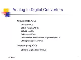
Types of DAC Circuits 1. Resistor String 2. N-Bit Binary Weighted Resistor 3. R-2R Ladder 4. PWM DAC
Resistor String DAC • 3 Bit Resistor String DAC • Components of a String DAC • Resistor String • Selection Switches • Opamp
Resistor String DAC • How many internal components would be needed to create an 8 bit resistor string DAC? Number of Resistors = Number of Switches = • Impractical for a DAC with more than a couple bits input.
Weighted Resistor DAC R 2R 4R 2nR R/2 - Vout + • Basic Idea: • Use a summing op-amp circuit • Use transistors to switch between high and ground • Use resistors scaled by two to divide voltage on each branch by a power of two
Weighted Resistor Example Summing op-Amp: • Vref = -2V • Digital word = 1010 • V1 = -2V • V2 = 0V • V3 = -2V • V4 = 0V • Rf = R/2 R V1 Rf 2R V2 4R V3 - Vout + 8R V4
Weighted Resistor Summary • Advantages • Simple • Fast • Disadvantages • Need large range of resistor values (2000:1 for 12-bit) with high precision in low resistor values • Need very small switch resistances • Summary • Use in fast, low-precision converter
R-2R DAC • Basic Idea: • Use only 2 resistor values • Use equal resistances in parallel to halve the resistance • Creates a series of voltage dividers cutting voltages in half • Another summing op-amp
R-2R Example • Digital word = 001 • V0 has two 2R resistances in parallel connected to ground • Equivalent of R between V0 and ground • V1 now has a resistance R to V0 and R to ground • V0 = V1/2 • V1 has two 2R resistances to ground • Equivalent of R between V1 and ground • V2 now has a resistance R to V1 and R to ground • V1 = V2/2 • V2 = Vref • V0 = V2/4 • V0 = Vref/4 • Vout = -V0/2 • Vout = -Vref/8
R-2R Summary • Advantages • Only 2 resistor values • Summary • Better than weighted resistor DAC
Pulse Width Modulation • Approximate analog signal by switching on/off at high frequency • Integral of output voltage from PWM ideally is the same as integral of desired output voltage • N-bit digital words updated at rate f • DAC clock must run at rate 2n*f • Example: • Desired output = 7V, supply voltage = 10V • Operate 10V at 70% duty cycle to approximate 7V • In practice: use counter, comparator, clock, integrator
PWM Summary • Advantages • All digital • Cheap • Disadvantages • High sampling rate required • Sensitive to clock variations • Summary • Best when load is a (relatively) slowly responding system
Errors • Gain Error • Offset Error • Full Scale Error • Linearity • Non-Monotonic Output Error • Settling Time and Overshoot • Resolution
Gain Error • Slope deviation from ideal gain • Low Gain Error: Step Amplitude is less than ideal • High Gain Error: Step Amplitude is higher than ideal
Offset Error • The voltage is offset from zero when all input bits are low
Full Scale Error • Combination of gain error and offset error
Non-Linearity • The linearity error is due to the fact that the resolution of the converter is not constant.
Non-linearity • The largest difference between the actual and theoretical output as a percentage of full-scale output voltage
It is the difference of tension obtained during the passage in the next digital code. Non-linearity • Should be 1 LSB in theory.
Non-monotonic Output Error • A form of non-linearity due to errors in individual bits of the input
Settling Time and Overshoot • Changes in input are not reflected immediately in the output • Lag times result
Resolution Errors • Inherent errors associated with the resolution • More Bits = Less Error and Greater Resolution • Less Bits = More Error and Less Resolution
Programmable gain OpAmps • Voltage controlled Amplifier (digital input, Vref as control) • Digitally operated attenuators (Vref as input, digital control)
Programmable Filters • Integrate DACs in filters • Variable cutoff frequency commanded by a digital signal
DAC Applications • Used at the end of a digital processing chain when analog signals are required • Digital Audio • CD Players, digital telephones, etc. • Industrial Control Systems • Motor speed, valves, etc. • Waveform Function Generators • Cruise Control
References • Alciatore, “Introduction to Mechatronics and Measurement Systems,” McGraw-Hill, 2003 • Horowitz and Hill, “The Art of Electronics,” Cambridge University Press, 2nd Ed. 1995 • http://www.me.gatech.edu/charles.ume/me6405Fall01/ClassNotes/DA_fall_01.ppt • http://products.analog.com/products/info.asp?product=AD7224 Analog Devices AD 7224 DAC General Overview and Specifications • http://courses.washington.edu/jbcallis/lectures/C464_Lec5_Sp-02.pdf D/A Converter Fundamentals and Definition Of Terms • http://www.eecg.toronto.edu/~kphang/ece1371/chap11_slides.pdf Data Converter Fundamentals