Download
1 / 57
570 likes | 724 Views
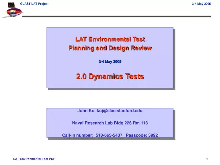
LAT Environmental Test Planning and Design Review 3-4 May 2005 2.0 Dynamics Tests. John Ku kuj@slac.stanford.edu Naval Research Lab Bldg 226 Rm 113 Call-in number: 510-665-5437 Passcode: 3992. Tue May 3 PM Agenda . 2.0 Dynamics Tests (John Ku) 1:00 pm 2.1 Sine Vibe

E N D
LAT Environmental Test Planning and Design Review 3-4 May 2005 2.0 Dynamics Tests John Ku kuj@slac.stanford.edu Naval Research Lab Bldg 226 Rm 113 Call-in number: 510-665-5437 Passcode: 3992
Tue May 3 PM Agenda • 2.0 Dynamics Tests (John Ku) • 1:00 pm 2.1 Sine Vibe • 1:00 2.1.1 Test Plan • 1:30 2.1.2 Test Configuration • 2:00 2.1.3 Test Logistics • 2:20 2.1.4 Open Issues • 2:30 pm 2.2 Acoustic • 2:30 2.2.1 Test Plan • 3:00 2.2.2 Test Configuration • 3:30 2.2.3 Test Logistics • 3:50 2.2.4 Open Issues • 4:00 pm 2.3 Weight and CG • 4:00 2.3.1 Test Plan • 4:10 2.3.2 Test Configuration • 4:15 2.3.3 Test Logistics • 4:25 2.3.4 Open Issues • 4:30 pm 2.4 Open Issues • To get through these 57 Slides in 4 hours, we must average 4.2 minutes/slide
Sine Vibration Test – Test Plan Overview • Objectives of the test are well understood by all • Verify the strength of the LAT and subsystem interfaces under PFQ loads and durations • Measure primary natural frequencies (fn) of the primary modes of the LAT • Determine transmissibility (Q) of the LAT • Validate the math model used for coupled loads analysis • Verify the workmanship and processes used in the manufacture and assembly • Test Plan • Third draft of test plan is out for review – first major update in over a year • Many technical details have been addressed in previous meetings – the current draft is very mature and should be released in 1-2 weeks • First comments in from GSFC mechanical branch have been minor and already incorporated • Instrumentation list is nearing completion, but not finished yet • Internal accelerometers defined and CAD layout complete • Strain gauges (16 channels) on flexures defined (NRL can accommodate up to 40 channels, ¼ bridge) • External accelerometer mathematical positions defined, but CAD layout needed
Sine Vibration Test – Test Plan Overview • Test Plan (Continued) • Entrance/Exit Criteria are well understood by all; from the test plan: • The sine vibe dynamic test is the first environmental test to be performed after arrival to NRL and the subsequent CPT. Criteria which must be met before this test can be executed are: • LAT mechanical integration is complete—all visual, dimensional, and torque testing has been complete, and all travelers verified to be complete. The LAT is in its flight configuration, except as detailed in Section 8.3. • All subsystem units/modules function—each subsystem has passed its CPT following removal from the shipping container. Any performance discrepancies have been clearly documented. • Ensure all E-GSE needed is installed and functioning. After moving and attaching the LAT to the vibration test equipment, ensure each subsystem has passed its LPT. All E-GSE cable harnesses have been removed from the LAT prior to test. • All test instrumentation is in place and functioning—instrumentation has been verified to be securely mounted in the correct locations and oriented in the correct direction, as defined in the test procedure, and electronics are working correctly, and reading out signals. Cable harnesses for this instrumentation are connected and properly restrained for the test • Pretest analysis which provides predictions for Fn and Q for significant modes at all test accelerometers • Following the sine vibration test, an LPT will be performed. Prior to breaking test configuration, the following criteria must be met: • Visual inspection of the LAT indicates that there is no visible damage to the LAT • Successful completion of the LPT verifies that all components and subsystems function properly after testing • Rough analysis of test data shows that all recorded data is useable for analysis purposes • Comparison of pre-test and post-test modal signatures match to within 5%, or at the discretion of the test director, showing that modal frequencies have not changed significantly as a result of the test.
Sine Vibration Test – Test Plan – Requirements • Test Requirements • Instrument Verification Plan • The tests will be performed to the levels published in the LAT environmental specification document, LAT-SS-00778 • The dynamics tests are to be performed in the mode in which the equipment will observe the environment • LAT will be launched in a “powered off” mode • The sine vibration tests will be performed with the article powered off
Sine Vibration Test – Test Configuration • The LAT is transported and supported on the TIP • TIP is already installed for all handling before and after test • TIP assembly uses SC flexures from Spectrum • TIP is designed to simulate SC flexure/top deck interface, so it provides a nearly flight-like interface for the test • Interface to both the slip table and expander head is by way of a simple bolt pattern that fits well with the LAT geometry X/Y-Axis Vibration Configuration Z-Axis Vibration Configuration
MGSE Requirements Flowing from Sine Vibe Test Plans • See the table, below, for a list of all MGSE/STE that is needed for conducting the sine vibe test • Test Interface Plate • TIP and mounting hardware capable of handling inertial loads of LAT during test • TIP bolt pattern and size compatible with expander head and slip table • TIP plate supported adequately to ensure stiff connection to slip table/expander head • Dust Tent • Capable of providing clean, dry environment before/during/after vibe testing • Provides clearance around LAT for unrestricted motion during vibe • Capable of being on/off-loaded from GPR to vibe table • Heat Pipe Restraining Plates • Supports DSHP/XLHP 3-way joints during vibe since Radiator VCHP’s are not mounted • Provides flight-like interface to simulate VCHP flange • Chill Bars • Capable of handling vibration loads (obviates need to de-/re-integrate them) MGSE/STE Needed for Sine Vibe Testing
Auxiliary Cooling and Mechanical Handling • Auxiliary cooling plans • LAT needs to be cooled during LPT’s between each vibe axis run and before and after • Chill Bars: one under each of the two X-wings on the Grid • X-LAT Aux Cooling: using fly-away cooling lines already mounted to X-LAT Plate • This is room-temperature cooling to remove LAT process heat • To simplify cooling connections, Chill Bars and X-LAT cooling will be designed to handle vibe loads • Hoses will be disconnected using quick-disconnect fittings • Handling and mechanical operating procedures • LAT lifting procedure • TIP mounting procedure • Dust tent handling and operating procedure • LAT auxiliary cooling system operating procedure
MGSE Issues for Sine Vibe Testing • Dust Tent • This is likely needed for sine vibe, but is still TBR • If needed, how will dust tent be supported off of the slip table/expander head around the LAT, while the LAT is vibed? • How do we access the LAT for electrical and aux. cooling interconnects before/after vibe testing? • How is the Dust Tent handled with the LAT • LAT is transported with the Tent hanging from the GPR • After integration on the slip table, the Tent will need to be re-positioned onto the vibe table base • Logistics in the vibe lab • Space is tight in the vibe lab, and the LAT MGSE is large • We will have 4 large-footprint objects in the lab nearly simultaneously • LAT on the TIP • GPR • 4 x 4 Lift Fixture • MGSE Cart • Vibe lab also has 2 vibe tables and the expander head which will need re-positioning during our test • We will be running through the handling logistics with paper dolls, then with the pathfinder, so we should be able to catch the problem areas early
TIP was analyzed for lift loads and dynamic performance (see FEA Mesh shown at left) High margins were calculated for both cases Rough calculations for the mounting shoes were performed, with more detailed analysis to follow Conservative hand calculations show high margins for strength and stiffness Rough calculations for the test stand have been performed, wth more detailed analysis to follow Concentrated on regions of highest load Design is extrememly stout, and calculations show corresponding high strength margins MGSE Structural Analysis Status
MGSE Structural Analysis – TIP – Lift case • The TIP is only attached to the mounting shoes by 16 screws, in a thinned section • When lifted, how much will the TIP sag from its own weight? 148 microns (0.6 mils) • How much stress is imparted from the prying loads? 3.02 MPa (241 MPa Yield)
MGSE Structural Analysis – TIP – Dynamic Performance Calculated First Mode = 417 Hz Required Performance: >225 Hz (1.5*150 Hz)
MGSE Structural Analysis – Test Stand Test Interface Plate LAT Radiator SC Strut simulators Test Stand Radiator
Sine Vibration Test – Test Plan – Constraints • EGSE Constraints • Cables • Disconnected during vibration • Must be long enough to reach LAT while mounted to either expander head or slip table • Cable trays or protection if laid on floor • Cart with EGSE Hardware • Portable, can be rolled out of the way • Power interface to lab?
Sine Vibration Test – Test Configuration • Mechanical Configuration • Radiators not attached • By agreement with the GPO, no mass simulators are needed • Mounted to GD/Spectrum Astro-provided test flexures • Test flexures will be proof tested at SLAC prior to GRID static test • TIP to interface test flexures and slip table/expander head • LAT Z-axis is always vertical • Access to connectors needed (scaffold around expander head?) on +X side • Layout needed to check cable run lengths • Electrical Configuration • SLAC purchased accelerometers are voltage type and have 10-32 connectors, with a special proprietary triax connector • Adapters will be needed to interface with NRL equipment • ACD accelerometer interface to be verified • Strain gauges do not have connectors (open leads) • EGSE needed for LPTs between axes (Rich Baun to define requirements)
Sine Vibration Test – Test Configuration – Instrumentation • Test instrumentation by subsystem, total of 57 channels, calibrated and installed by SLAC I&T, final checkout by NRL
Sine Vibration Test – Test Configuration – Instrumentation
Sine Vibration Test – Test Configuration – Instrumentation
Four strain gauges installed per flexure for a total of 16 strain gauge channels Assumed to be 120 Ohm, ¼ bridge, GF=2 Strain gauges should be temperature compensated if possible The gauges and data acquisition equipment should be sized to capture a maximum strain of 2500 microstrain (titanium has a yield strain of 7500 microstrain) and have a 0.25% precision (6 microstrain error) The combination of strain gauges will allow measurement of axial strain and bending strain Shear strain will not be directly measured, but may be ascertained from the combined strain readings of the two legs and pre-test analysis Sine Vibration Test – Test Configuration – Instrumentation
Sine Vibration Test Planning: Detailed Sequence • Pre-test Activities • Move dolly into position in vibration lab and disconnect LAT from dolly (SLAC-IFCT) • Lift LAT and TIP onto expander head, and torque bolts (NRL) • Cable Hook-ups and system checkouts • Electrical connections to shaker system and accel tap checks (NRL) • Electrical connections to EGSE and perform LPT on expander head (SLAC) • Z-Axis Vibration Test • Low-level Signature Sine Sweep to 150 Hz (sweep up and down) • Set-up sheet printouts (NRL), verification and approval (SLAC) • If LPT results are okay, disconnect EGSE cables • Run test • Output FRF data (NRL) • Review Data (SLAC) • Determine notching, if needed • Provide feedback to test conductor • Check pass/fail criteria for Modal Test requirement • Give OK to proceed (SLAC), or decide alternate action is needed • Half-level run to 50 Hz • Set-up sheet printouts (NRL), verification and approval (SLAC) • Run test • Output data hardcopies (NRL) • Review Data (SLAC) • Check notching and adjust, if needed • Provide feedback to test conductor • Give OK to proceed (SLAC), or decide alternate action is needed
Sine Vibration Test Planning: Detailed Sequence (cont.) • Z-Axis Vibration Test (continued) • Full-level run to 50 Hz • Set-up sheet printouts (NRL), verification and approval (SLAC) • Run test • Output data hardcopies (NRL) • Review Data (SLAC) • Check peak levels • Check pass/fail criteria for Modal Test requirement • Give OK to proceed (SLAC), or decide alternate action is needed • Low-level Signature Sine Sweep to 150 Hz • Set-up sheet printouts (NRL), verification and approval (SLAC) • Run test • Output data overlays (NRL) • Review Data (SLAC) • Re-Check pass/fail criteria for Modal Test requirement • Concurrent with data review, hook-up EGSE and perform LPT • If data review and LPT are good, Give OK to break configuration, or decide is alternate action is needed • Post- Z-Test / Pre- X-Test Activities • Disconnect all electrical connections • Remove mounting bolts and move LAT from expander head and set on handling dolly • Remove expander head, rotate shaker to horizontal position and attach drive bar to slip table • Lift LAT and TIP onto slip table for X-axis vibration and torque bolts • Hook-up accelerometers only and perform vibration control system checkout (no EGSE hook-up here)
Y Y X X LAT LAT Sine Vibration Test Planning: Detailed Sequence (cont.) • X-Axis Vibration Test • Low-level Signature Sine Sweep to 150 Hz • Same steps as Z-axis test • Give OK to proceed (SLAC), or decide alternate action is needed • Half-level run to 50 Hz • Same steps as Z-axis test • Give OK to proceed (SLAC), or decide alternate action is needed • Full-level run to 50 Hz • Same steps as Z-axis test • Give OK to proceed (SLAC), or decide alternate action is needed • Low-level Signature Sine Sweep to 150 Hz • Same steps as Z-axis test • Concurrent with data review, hook-up EGSE and perform LPT • If data review and LPT are good, Give OK to break configuration, or decide is alternate action is needed • Post- X-Test / Pre- Y-Test Activities • Disconnect EGSE electrical connections, leaving Accel cables connected • Remove mounting bolts, lift and rotate LAT in place • Lower LAT to slip table and torque bolts • Perform vibration control system checkout (no EGSE hook-up here) Shaker Slip Table Shaker Slip Table
Sine Vibration Test Planning: Detailed Sequence (cont.) • Y-Axis Vibration Test • Low-level Signature Sine Sweep to 150 Hz • Same steps as X-axis test • Give OK to proceed (SLAC), or decide alternate action is needed • Half-level run to 50 Hz • Same steps as X-axis test • Give OK to proceed (SLAC), or decide alternate action is needed • Full-level run to 50 Hz • Same steps as X-axis test • Give OK to proceed (SLAC), or decide alternate action is needed • Low-level Signature Sine Sweep to 150 Hz • Same steps as X-axis test • Concurrent with data review, hook-up EGSE and perform LPT • If data review and LPT are good, Give OK to break configuration, or decide is alternate action is needed • Post- Y-Test Activities • Disconnect all electrical connections • Remove mounting bolts, lift and set LAT on handling dolly • Attach LAT to handling dolly
Sine Vibration Test – Configurations – Deviations From Flight • The Radiators are not integrated to the LAT for this test. • Structural interactions between the Radiators and the Grid are not captured • This interface will be strength verified at the subsystem level • Coverplates to constrain the down spout heat pipes (DSHPs) and X-LAT heat pipes (XLHPs) to prevent relative motion to the Grid • This interface will be strength verified at the subsystem level • The LAT is mounted to STE using test flexures which simulate the flight connection to the SC • The STE and test flexures will be included in the pre-test FEA analysis, so its impact on the response of the LAT will be understood. • Since the Radiators and SC are not included in this test, not all flight cable harnesses and supports will be integrated for this test • These cables and their associated support brackets will not be adequately verified by this test • Workmanship for these flight connections and harnesses will be accomplished with the Observatory level sine vibration test.
Sine Vibration Test – Document List and Status • LAT-MD-00408: LAT Instrument Performance Verification Plan • LAT-MD-02717: LAT Environmental Test Sequence • LAT-MD-01196: LAT Dynamics Test Plan • LAT-MD-01533: LAT EGSE Plan • LAT-MD-00649: LAT Transportation and Handling Plan • LAT-MD-00404: LAT Contamination Control Plan • LAT-SS-00778: LAT Environmental Spec • LAT-TD-00890: LAT Instrumentation Plan
Sine Vibration Test – Test Logistics • Test Personnel • Test support personnel have been identified (to be verified) • Test Director: John Ku (SLAC) • Test Conductor: Bob Haynes (NRL) • Discipline Lead: Jim Haughton (NRL) • Facility Manager:Bill Raynor (NRL) • MGSE Lead: Martin Nordby (SLAC) • EGSE Lead: Mike Huffer (SLAC) • Test Script Lead: Rich Baun (SLAC) • High-bay operations: Paul Dizon (NRL) • Quality Assurance: Joe Cullinan (or Doug Bartholomew) (SLAC) • I&T: Ken Fouts (SLAC) • Subcommittees will be assembled from the appropriate personnel above, with expert consultation brought in if needed • Potential Vibration Experts: Paul Baird; Chris Fransen; Bill Haile
Sine Vibration Test – Test Logistics • Many logistics have already been worked out; these remain: • Complete and release drawings/model of slip table and expander head • Verify slip table and expander head size, inserts and pattern • Clearance to off-load frame on expander head • Verify that Test Interface Plate fits completely on expander head • Verify that LAT clears bracket parts on slip table • Develop paper doll work-up to verify we have floor space for 2 carts, GPR, and 4x4 Lift Fixture • Lay out EGSE cable routing and locate EGSE crates • Identify what contamination and humidity control is needed in vibe facility • Is GN2 purge neccesary? • Cleanliness (need blanket?) • CG Alignment / sensitivity of equipment to offsets (by analysis TBD) • Instrumentation patch panels and cable supports (ensure all connectors interfaces) • Complete detailed design and analysis of TIP and flexure mount brackets (In-process) • Verify response / control channel capability (NRL) • Contingencies • Need to be prepared to perform a modal test if the LAT frequencies do not meet expectations • Modal test will not need additional instrumentation • May require the use of portable shaker with stinger to RMB or other hardpoint • Impact to schedule is not believed to be more than one day of testing (but rigorous post test data reduction will be needed)
Sine Vibration Test – Open Issues • Complete structural analysis of MSGE • Complete pre-test analysis, including a simulation of LAT on fixtures • 10 action items are open and being tracked. • 9 have clear closure paths and are actively being worked on • 1 action not addressed yet is not a high priority, as MGSE has not been designed yet
Acoustic Test – Test Plan Overview • Objectives of the test are well understood by all • The objective of the acoustic test is to demonstrate that the fully integrated LAT is capable of withstanding acoustic noise loads, simulating launch conditions. • A secondary objective is to verify the acoustic analysis, i.e. that the LAT components were qualified to high enough levels of Random vibration • Test Plan • Third draft of test plan is out for review – first major update in over a year • Many technical details have been addressed in previous meetings – the current draft is very mature and should be released in 1-2 weeks • First comments in from GSFC mechanical branch have been minor and already incorporated • Instrumentation list is nearing completion, but not finished yet • Internal accelerometers defined and CAD layout complete • Strain gauges (16 channels) on flexures defined (NRL can accommodate up to 40 channels, ¼ bridge) • External accelerometer mathematical positions defined, but CAD layout needed
Acoustic Test – Test Plan Overview • Test Plan (Continued) • Entrance/Exit Criteria are well understood by all; from the test plan: • The LAT acoustic test is performed immediately following the LAT sine vibe test. Criteria which must be met before this test can be executed are: • LAT mechanical integration is complete—all visual, dimensional, and torque testing has been complete, and all travelers verified to be complete. The LAT is in its flight configuration, except as detailed in Section 10.3. • All subsystem units/modules function—each subsystem has passed its CPT following removal from the shipping container. Any performance discrepancies have been clearly documented. • Ensure all E-GSE needed is installed and functioning. After moving and attaching the LAT to the vibration test equipment, ensure each subsystem has passed its LPT. All E-GSE cable harnesses have been removed from the LAT prior to test. • All test instrumentation is in place and functioning—instrumentation has been verified to be securely mounted in the correct locations and oriented in the correct direction, as defined in the test procedure, and electronics are working correctly, and reading out signals. Cable harnesses for this instrumentation are connected and properly restrained for the test. • Following the acoustic test, an LPT will be performed. The criteria for declaring a successful completion of the acoustic test are:: • Visual inspection of the LAT—indicating that there is no visible damage to the LAT • Successful completion of the LPT—verifying that all components and subsystems function properly after testing • Preliminary analysis of test data—verify that all recorded data is useable for analysis purposes • No significant mode shifts—pre- and post-test signatures match within 5% showing modal frequencies have not changed as a result of testing
Acoustic Test – Test Plan – Requirements • Test Requirements • Instrument Verification Plan • The tests will be performed to the levels published in the LAT environmental specification document, LAT-SS-00778 • The dynamics tests are to be performed in the mode in which the equipment will observe the environment • LAT will be launched in a “powered off” mode • The acoustic test will be performed with the article powered off
MGSE/STE for Acoustic Testing • LAT (on the TIP) is mounted on the Test Stand for acoustic testing • LAT + TIP mounts to Test Stand then Radiators are integrated • LAT is rolled into the acoustic chamber, then jacked off its casters • Dust Tent remains over the LAT for the entire operation, including during testing (TBR) • SC top deck simulator • A circular honeycomb-core panel is mounted in the hole of the TIP • This simulates the acoustic behavior of the SC top deck • There is free access to the underside of the TIP through the Test Stand to integrate and instrument this Test Interface Plate LAT Radiator SC Strut simulators Test Stand Radiator Acoustic Test Configuration
MGSE Requirements Flowing from Acoustic Test Plans • See the table, below, for a list of all MGSE/STE that is needed for conducting the acoustic test • Test Interface Plate • TIP accommodates a top deck acoustic simulator • Top deck acoustic simulator adequately simulates the acoustic behavior of the SC • Dust Tent • Capable of providing clean, dry environment before/during/after acoustic testing • Provides clearance around LAT • Does not impact the acoustic response of the LAT or acoustic environment in the chamber during testing • SC Strut Simulators • Provides flight-like interface to simulate SC struts that support the Radiators • Interface with Radiator at flight interface, and with Test Stand • Chill Bars • Capable of handling acoustic loads (obviates need to de-/re-integrate them) MGSE/STE Needed for Acoustic Testing
Auxiliary Cooling and Mechanical Handling • Auxiliary cooling plans • LAT needs to be cooled during LPT’s before and after acoustic testing • Chill Bars: one under each of the two X-wings on the Grid • X-LAT Aux Cooling: using fly-away cooling lines already mounted to X-LAT Plate • This is room-temperature cooling to remove LAT process heat • To simplify cooling connections, Chill Bars and X-LAT cooling will be designed to handle acoustic loads • We may be able to leave all hoses and fittings connected during the test (TBR), otherwise will quick-disconnect them • Handling and mechanical operating procedures • LAT lifting procedure • Radiator integration procedure • Test Stand handling and operating procedure • Dust tent handling and operating procedure • LAT auxiliary cooling system operating procedure
MGSE Issues for Acoustic Testing • Dust Tent • This is likely needed for acoustic testing, but is still TBR • If needed, what is impact of dust tent on acoustic environment in the chamber? • Dust tent will need to be designed to not overly-attenuate sound pressure levels • Transportation issues • The acoustic chamber has a ¾” door sill/threshold • We plan to build a ramp to roll up and over the sill • This will definitely by prototyped with the pathfinder, since the LAT c.g. is moderately high • Test Stand will be moved into the room with an electric forklift • We need to verify that it can position the LAT adequately
Acoustic Test – Test Plan – Constraints • EGSE Constraints • Cables • Disconnected during vibration • Must be long enough to reach LAT while mounted to either expander head or slip table • Cable trays or protection if laid on floor • Cart with EGSE Hardware • Portable, can be rolled out of the way • Power interface to lab?
Acoustic Test – Test Configuration • Mechanical Configuration • Radiators attached (with flight thermal joint) • Need to ensure thermal joint has enough time to cure (7 days RT) • Mounted to GD/Spectrum Astro-provided test flexures • Test flexures will be proof tested at SLAC prior to GRID static test • Mounted on LAT acoustic test stand • LAT Z-axis is vertical • Access to connectors needed (ladder around MGSE) on +X side • Layout needed to check cable run lengths • Electrical Configuration • SLAC purchased accelerometers are voltage type and have 10-32 connectors, with a special proprietary triax connector • Adapters will be needed to interface with NRL equipment • ACD accelerometer interface to be verified • Strain gauges do not have connectors (open leads) • EGSE needed for LPTs between axes (Rich Baun to define requirements)
Acoustic Test – Test Configuration – Instrumentation • Test instrumentation by subsystem, total of 57 channels, calibrated and installed by SLAC I&T, final checkout by NRL
The STE will be centered in the acoustic chamber, rotated to an angle of approximately 20-30 degrees, as measured between the Radiator surface and chamber sidewall Additionally, there will be a plastic sheet placed under the STE to help identify any items that may come loose as a result of the acoustic vibration. Acoustic Chamber M2, ACD Mid-pnl ~36” M1, ACD Mid-pnl M5, RAD Mid-pnl M3, ACD Mid-pnl M6, RAD Mid-pnl LAT M4, ACD Mid-pnl M7, monitor only Acoustic Test – Test Configuration – Instrumentation
Acoustic Test Planning: Detailed Sequence • Pre-test Activities • Chamber Setup and empty cell calibration • This is needed to verify the test cell is clean and ready to accept the LAT for testing • The empty cell calibration will verify that the specified sound pressure levels can be achieved • Move LAT on dolly (radiators already installed) into chamber and set orientation to the appropriate angle • Cable Hook-ups and system checkouts • Electrical connections to shaker system and accel tap checks (NRL) • Electrical connections to EGSE and perform LPT on expander head (SLAC) • LPT on acoustic test stand • Low-Level run at -6 dB for 30 seconds (establish pre-test signature, review data) • Set-up sheet printouts (NRL), verification and approval (SLAC) • If LPT results okay, disconnect EGSE cables and close chamber door • Purge chamber of air • Run Test • Output Data, accel ASD’s and strain gauge SSD’s (NRL) • Review data (SLAC) • Check for “dead” channels • Review mic average for level and chamber uniformity • Review Grms values for obvious anomalies • Give Okay to proceeed (SLAC), or decide if alternate action is needed
Acoustic Test Planning: Detailed Sequence (cont.) • Full-Level run at -0 dB for 60 seconds (impart full SPL, check SPL, linearity, review data) • Set-up sheet printouts (NRL), verification and approval (SLAC) • Run Full level Test • As level steps up to -3dB, check critical channel linearity and record data • Hold at full level for 60 seconds • Immediately following full level run, perform low level run • Do not review data between full level and post-test low level run • Output Data accel ASD’s and strain gauge SSD’s (NRL) • Review data (SLAC) • Check for “dead” channels • Review mic average that PFQ level is met and chamber uniformity • Review Grms values for linearity • Give Okay to proceeed (SLAC), or decide if alternate action is needed
Acoustic Test Planning: Detailed Sequence (cont.) • Low-Level run at -6 dB for 30 seconds (Signature check, review data, complete axis) • Output Data (NRL) • Review data (SLAC) • Check for “dead” channels • Review mic average for level and chamber uniformity • Review pre- and post- test overlays for frequency shifts and amplitude changes • Give Okay to proceeed (SLAC), or decide if alternate action is needed • Post- Acoustic Test Activities • Fill chamber with air (may be done automatically following final low-level run) • Connect EGSE and perform LPT • Visually inspect plastic sheet under LAT • If everything looks okay, give okay to break configuration • Disconnect all electrical connections • Move LAT out of chamber
Acoustic Test – Configurations – Deviations From Flight • The LAT is mounted to STE, which is intended to simulate the influence of the SC volume and geometric proximity on acoustic pressures immediately adjacent to significant LAT surfaces, such as the Radiators and XLAT plate • The SC top deck and lower radiator strut mounts were identified as the critical regions for SC simulation • The top deck simulator will be of the same construction as the SC top deck and will be attached to the TIP MGSE • The lower radiator strut mounts will have a similar interface with the radiators and the stiffnesses will be approximated, but cross-coupling and stiffness differences will not be captured in this test • SC-LAT cabling is not connected for this test, so these connections, the cable harnesses, and the attachment methods are not verified as part of this test • These will be verified at the Observatory acoustic test
Acoustic Test – Document List and Status • LAT-MD-00408: LAT Instrument Performance Verification Plan • LAT-MD-02717: LAT Environmental Test Sequence • LAT-MD-01196: LAT Dynamics Test Plan • LAT-MD-01533: LAT EGSE Plan • LAT-MD-00649: LAT Transportation and Handling Plan • LAT-MD-00404: LAT Contamination Control Plan • LAT-SS-00778: LAT Environmental Spec • LAT-TD-00890: LAT Instrumentation Plan
Acoustic Test – Test Logistics • Test Personnel • Test support personnel have been identified (to be verified) • Test Director: John Ku (SLAC) • Test Conductor: Bob Haynes (NRL) • Discipline Lead: Jim Haughton (NRL) • Facility Manager:Bill Raynor (NRL) • MGSE Lead: Martin Nordby (SLAC) • EGSE Lead: Mike Huffer (SLAC) • Test Script Lead: Rich Baun (SLAC) • High-bay operations: Paul Dizon (NRL) • Quality Assurance: Joe Cullinan (or Doug Bartholomew) (SLAC) • I&T: Ken Fouts (SLAC) • Subcommittees will be assembled from the appropriate personnel above, with expert consultation brought in if needed • Potential Vibration Experts: Paul Baird; Chris Fransen; Bill Haile
Acoustic Test – Open Issues • Many logistics have been closed already; the logistics that still need consideration are: • Lip at threshold (how to transport into room) • Accommodation for moving Test Stand over ½” door sill • Use pneumatic wheels or air bearings? • Cleanliness (need blanket?) – is rating worse than 100K? • Instrumentation feedthrough and cable supports • Is a dust tent needed around LAT in acoustic chamber • What type of panels are needed in/around LAT to simulate SC response • Complete structural analysis of MSGE • Complete pre-test analysis • Verify top plate simulator attached to TIP MGSE adequately replicates SC response • 5 action items are open and being tracked. • All actions have clear closure paths and are actively being worked on
Weight and CG Test – Test Plan Overview • Objectives • The primary objective of this test is to measure and/or calculate the overall mass and CG of the fully integrated LAT, to verify that it meets the IRD [433-IRD-0001] requirements of: • Mass is less than 3000 kg • Z-cg is a maximum of 185mm above the LAT Interface Plane (LIP) • Because of the difficult involved in measuring Zcg, this requirement will be verified through calculations, based on measurements of all LAT constituents. • From the Xcg and Ycg measurements and comparison with calculated values, an appropriate confidence level can be established and applied to the Zcg calculations. • X-cg and Y-cg are within 20mm of LAT Coordinate System (LCS) Z-axis • A secondary objective is to verify measured mass properties match well when compared with the math model mass matrix. • Due to the complexity of measuring moments of inertia, only mass and CG properties will be validated. Differences will be reconciled by updating the math model to reflect measured values • Since structural dynamics is intimately tied with mass and stiffness, mass property updates are important to preserve the true dynamic behavior of the LAT. • Test Plan • This is a new addition to the test plan draft 3 • Many technical details have been addressed in previous meetings – the current draft is very mature and should be released in 1-2 weeks • All needed instrumentation has been identified, but MGSE design is still needed
Weight and CG Test – Test Plan Overview • Test Plan (Continued) • Entrance/Exit Criteria; from the test plan: • The LAT mass properties test is performed following the LAT thermal vacuum test and the subsequent CPT and removal of the radiators. Criteria which must be met before this test can be executed are: • LAT Radiators have been removed and the LAT, Flexures and TIP have been moved into the mass properties test area—visual inspection verifies that all the LAT has been re-configured correctly. All travelers verified to be complete. The LAT is in its flight configuration, except as detailed in Section 10.3, below. • All subsystem units/modules function—each subsystem has passed its CPT following TVAC. Any performance discrepancies have been clearly documented. • All non-fly-away accelerometers and other test instrumentation, cables and harnesses are removed. • Following the mass properties test, an aliveness will be performed. The criteria for declaring a successful completion of the mass properties test are: • Visual inspection of the LAT—indicating that there is no visible damage to the LAT • Successful completion of the aliveness test—verifying that all components and subsystems are still properly interconnected. • Preliminary analysis of test data—verify that all recorded data is useable for analysis purposes
Weight and CG Test – Test Plan – Constraints • MGSE Constraints • Platform to distribute weight into three load cells • Must be stiff enough to carry load from TIP (four points) to load cells (three points), i.e. to evenly distribute load from the four flexures • Must be light enough to not affect load cell accuracy (use load cells with highest possible accuracy and precision; load cell precision generally goes down with increased capacity) • Must have a way to precicely locate the LAT and TIP with respect to some arbitrary reference coordinate system • Must be able to accommodate the LAT in 0 and 90 degree orientations • EGSE Constraints • Cables • Disconnected during vibration • Cart with EGSE Hardware • Portable, can be rolled out of the way • Power interface to lab?