Download
1 / 14
160 likes | 608 Views
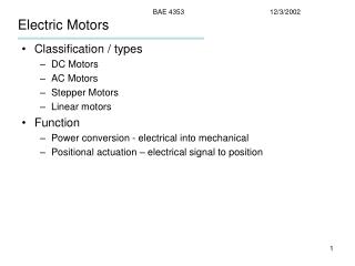
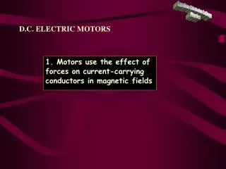
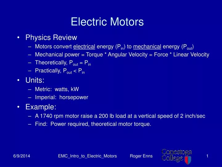
Electric Motors. Physics Review Motors convert electrical energy (P in ) to mechanical energy (P out ) Mechanical power = Torque * Angular Velocity = Force * Linear Velocity Theoretically, P out = P in Practically, P out < P in Units: Metric: watts, kW Imperial: horsepower

E N D
Electric Motors • Physics Review • Motors convert electrical energy (Pin) to mechanical energy (Pout) • Mechanical power = Torque * Angular Velocity = Force * Linear Velocity • Theoretically, Pout = Pin • Practically, Pout < Pin • Units: • Metric: watts, kW • Imperial: horsepower • Example: • A 1740 rpm motor raise a 200 lb load at a vertical speed of 2 inch/sec • Find: Power required, theoretical motor torque. EMC_Intro_to_Electric_Motors Roger Enns
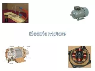
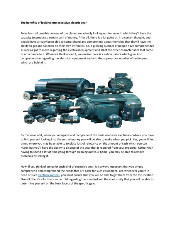
Electric Motor Types • AC • Induction motors • Shaded pole • Capacitor start • Gearmotors • Synchronous • DC • Shunt-wound • Series-wound • Gearmotors • Brushless About 2/3 of the electrical energy generated in the US is consumed by motors, over ½ of this by induction motors. EMC_Intro_to_Electric_Motors Roger Enns
NEMA – National Electrical Manufacturers Association • Sets North American standards for electric motors • Motor Ratings (power output, typically in hp) • Ratings depend on motor classification, overload allowance • Actual motor power capability > rating • Frame size • Physical size of motor, interface, mounting, shaft size, etc. • Housing protection/classification • Selected based on environment, code requirements, etc. EMC_Intro_to_Electric_Motors Roger Enns
Motor Terminology stator & rotor – a mechanical distinction field & armature – an electrical distinction EMC_Intro_to_Electric_Motors Roger Enns
AC Alternators • Basic Principle • As a conductor (wire) moves across a magnetic field, a voltage is produced causing current to flow in the wire. EMC_Intro_to_Electric_Motors Roger Enns
DC Generators • Basic Principle • As a conductor (wire) moves across a magnetic field, a voltage is produced causing current to flow in the wire. EMC_Intro_to_Electric_Motors Roger Enns
DC Generators cont’d. If a single conductor were rotated through a magnetic field, AC voltage would be produced Commutator: Segmented conductor that effectively reverses the polarity of the rotor every 180 degrees. Results in ‘lumpy’ DC voltage produced. Multiple rotor coils used to smooth the output. EMC_Intro_to_Electric_Motors Roger Enns
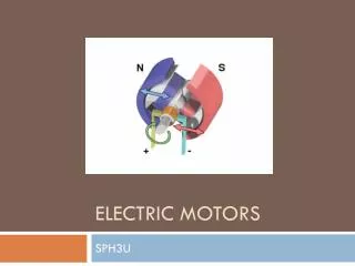
DC Motors • Reverse the operation of the generator by: • Applying DC voltage to the brushes. • Magnet field created is by current in rotor windings. • This magnetic field is attracted/repelled by the corresponding stator field. • Stator field may be created by permanent or electo-magnets. • As motor turns, commutator switches between active rotor windings to maximize motor torque. EMC_Intro_to_Electric_Motors Roger Enns
DC Motors EMC_Intro_to_Electric_Motors Roger Enns
Counter EMF • As the DC motor turns, a voltage is induced within the coil windings. This induced voltage opposed the applied voltage to the machine. • Induced voltage is known as “Counter EMF”, typically shown as E0 Z = # of conductors in winding n = RPM of machine Φ = Flux per pole EMC_Intro_to_Electric_Motors Roger Enns
Counter EMF Cont’d • At startup, full applied voltage is present across motor. As motor starts to turn, it immediately acts as a generator, whose counter EMF opposes the applied voltage. • When counter EMF generated = Applied Voltage, maximum theoretical motor speed is attained. Example: Motor has a winding made up of 50 coils with 10 conductors per coil. Assuming flux per pole = 0.02, find motor speed as a function of applied voltage. EMC_Intro_to_Electric_Motors Roger Enns
Electrical Analysis of DC Motors • Armature Current (IA) = (Es-E0)/R • At startup, E0 = 0, therefore very high initial startup current – may be 20 to 30 times normal operating current • DC motor starters often use current limiting techniques. EMC_Intro_to_Electric_Motors Roger Enns
Shunt-Wound DC Motor • Field windings in parallel with armature • High field resistance. • Nearly constant speed operation from no-load to full-load EMC_Intro_to_Electric_Motors Roger Enns
Series Wound DC Motor • Field windings in series with armature • Low field resistance – must conduct armature current. • Low-speed under high load. High-speed under low load. • DO NOT OPERATE UN-LOADED!! EMC_Intro_to_Electric_Motors Roger Enns