Download
1 / 42
440 likes | 754 Views
Chapter 4 Network Layer. A note on the use of these ppt slides:

E N D
Chapter 4Network Layer • A note on the use of these ppt slides: • We’re making these slides freely available to all (faculty, students, readers). They’re in powerpoint form so you can add, modify, and delete slides (including this one) and slide content to suit your needs. They obviously represent a lot of work on our part. In return for use, we only ask the following: • If you use these slides (e.g., in a class) in substantially unaltered form, that you mention their source (after all, we’d like people to use our book!) • If you post any slides in substantially unaltered form on a www site, that you note that they are adapted from (or perhaps identical to) our slides, and note our copyright of this material. Thanks and enjoy! JFK/KWR • Edited by Lindsay, Marga, and Sarah - March 2003 • All material copyright 1996-2002 • J.F Kurose and K.W. Ross, All Rights Reserved Computer Networking: A Top Down Approach Featuring the Internet, 2nd edition. Jim Kurose, Keith RossAddison-Wesley, July 2002.
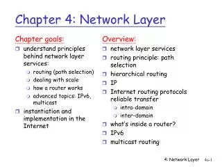
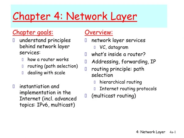
Chapter 4 roadmap 4.1 Introduction and Network Service Models 4.2 Routing Principles 4.3 Hierarchical Routing 4.4 The Internet (IP) Protocol 4.5 Routing in the Internet • 4.5.1 Intra-AS routing: RIP and OSPF • 4.5.2 Inter-AS routing: BGP 4.6 What’s Inside a Router? 4.7 IPv6 4.8 Multicast Routing 4.9 Mobility
Intra-AS Routing • Routing within an Autonomous System (AS) • Also known as Interior Gateway Protocols (IGP) • Most common Intra-AS routing protocols: • RIP: Routing Information Protocol • OSPF: Open Shortest Path First • IGRP: Interior Gateway Routing Protocol (Cisco proprietary)
RIP ( Routing Information Protocol) • Distance vector algorithm • Distance/Cost metric: • Each link has a cost of 1. • Maximum path cost is 15 – limits use of RIP to AS’s with a diameter of fewer than 15 hops. • Distance vectors: exchanged among neighbors every 30 sec via RIP Response Messages (also called advertisements) • Each advertisement: list of up to 25 destination routers and their distances from the router • Each forwarding table has at least one row for forwarding to networks outside the AS
RIP: Example z w x y A D B C Destination Network Next Router Num. of hops to dest. w A 2 y B 2 z B 7 x -- 1 …. …. .... Routing table in D
z y x w A D B C RIP: Example Dest Next hops w - - x - - z C 4 …. … ... Advertisement from A to D Destination Network Next Router Num. of hops to dest. w A 2 y B 2 z B A 7 5 x -- 1 …. …. .... Routing table in D
RIP: Link Failure and Recovery • If no advertisement heard after 180 sec --> neighbor/link declared dead • routes via neighbor invalidated • new advertisements sent to neighbors • neighbors in turn send out new advertisements (if tables changed) • link failure info quickly propagates to entire net • poison reverse used to prevent ping-pong loops • Routers can request info from neighbors about cost to a given destination using a request message • Request and response messages are sent over UDP and UDP Packet is carried in a standard IP packet
routed routed RIP Table processing • RIP routing tables managed by application-level process called routed Transprt (UDP) Transprt (UDP) network forwarding (IP) table network (IP) forwarding table link link physical physical
RIP Table example (continued) Router: giroflee.eurocom.fr Destination Gateway Flags Ref Use Interface -------------------- -------------------- ----- ----- ------ --------- 127.0.0.1 127.0.0.1 UH 0 26492 lo0 192.168.2. 192.168.2.5 U 2 13 fa0 193.55.114. 193.55.114.6 U 3 58503 le0 192.168.3. 192.168.3.5 U 2 25 qaa0 224.0.0.0 193.55.114.6 U 3 0 le0 default 193.55.114.129 UG 0 143454 • Three attached destination networks (LANs) • Router only knows routes to attached LANs • Default router used to go to any network not explicitly entered in the forwarding table • Route multicast address: 224.0.0.0 • Loopback interface (for debugging)
OSPF (Open Shortest Path First) • “open”: publicly available • Uses Link State algorithm • LS packet broadcasting • Topology map (directed graph) at each node • Route computation for forwarding table uses Dijkstra’s algorithm • OSPF advertisement carries one entry per neighbor router. • Individual link costs specified by the administrator • If all are set to 1, we have minimum hop routing • Link weights are set to be inversely proportional to link capacity. This discourages traffic on low bandwidth links • Advertisements disseminated to entire AS (via flooding) • Advertisements are carried in OSPF messages directly over IP (rather than TCP or UDP). Must implement RMT
OSPF “advanced” features (not in RIP) • Security: all OSPF messages authenticated (to prevent malicious intrusion) • Multiple same-cost paths allowed (only one path in RIP) • Integrated uni- and multicast support: • Multicast OSPF (MOSPF) uses same topology data base as OSPF • Hierarchical OSPF in large domains.
Hierarchical OSPF • Two-level hierarchy: local area, backbone. • Link-state advertisements only in area • each node has detailed area topology • Area border routers:“summarize” distances to nets in own area, advertise to other Area Border routers. • Backbone routers: • run OSPF routing limited to backbone. • Route between areas in the AS • Boundary routers: • in backbone • all outgoing packets are routed to boundary router if going to another AS
Inter-AS routing in the Internet: BGP BGP provides for routing among autonomous systems
Internet inter-AS routing: BGP • BGP (Border Gateway Protocol):the de facto standard • Path Vector protocol: • similar to Distance Vector protocol • each Border Gateway broadcast to neighbors (peers) entire path (i.e., sequence of AS’s) to destination • BGP routes to networks (ASs), not individual hosts • E.g., Gateway X may send its path to dest. Z: Path (X,Z) = X,Y1,Y2,Y3,…,Z
Internet inter-AS routing: BGP Suppose: gateway X send its path to peer gateway W • W may or may not select path offered by X • cost, policy (don’t route via competitors AS), loop prevention reasons. • If W selects path advertised by X, then: Path (W,Z) = w, Path (X,Z) • Note: X can control incoming traffic by controlling its route advertisements to peers: • e.g., don’t want to route traffic to Z -> don’t advertise any routes to Z
BGP: controlling who routes to you • X,W,Y are stub networks (all traffic entering them must be destined for them and all traffic exiting them must have originated there.) • X is dual-homed: attached to two networks • X does not want to route from B via X to C • .. so X will not advertise to B a route to C
BGP: controlling who routes to you • A advertises to B the path AW • B advertises to X the path BAW • Should B advertise to C the path BAW? • No way! B gets no “revenue” for routing CBAW since neither W nor C are B’s customers • B wants to force C to route to w via A • B wants to route onlyto/from its customers!
BGP operation Q: What does a BGP router do? • Receiving and filtering route advertisements from directly attached neighbor(s). • Route selection. • To route to destination X, which path (of several advertised) will be taken? • Sending route advertisements to neighbors.
BGP messages • BGP messages exchanged using TCP. • BGP messages: • OPEN: opens TCP connection to peer and authenticates sender • UPDATE: advertises new path (or withdraws old) • KEEPALIVE: keeps connection alive in absence of UPDATES; also ACKs OPEN request • NOTIFICATION: reports errors in previous msg; also used to close connection
Why different Intra- and Inter-AS routing ? Policy: • Inter-AS: admin wants control over how its traffic routed, who routes through its net. • Intra-AS: single admin, so no policy decisions needed Scale: • hierarchical routing saves table size, reduced update traffic Performance: • Intra-AS: can focus on performance • Inter-AS: policy may dominate over performance
Chapter 4 roadmap 4.1 Introduction and Network Service Models 4.2 Routing Principles 4.3 Hierarchical Routing 4.4 The Internet (IP) Protocol 4.5 Routing in the Internet 4.6 What’s Inside a Router? 4.7 IPv6 4.8 Multicast Routing 4.9 Mobility
Router Architecture Overview Two basic router functions: • run routing algorithms/protocol (RIP, OSPF, BGP) • switching datagrams from incoming to outgoing link
High-Level Router Architecture • Input Ports: • Physical layer functionality, terminates incoming physical link • Interoperates with the data link layer • Performs lookup and forwarding functions • In practice, multiple ports are often gathered together in a single line card within a router
High Level Router Architecture • Switching Fabric: • Connects the router’s input ports to its output ports • Output Ports: • Stores packets forwarded to it through the switching fabric • Routing Processor: • Executes the routing protocols • Maintains the routing information and forwarding tables • Performs network management functions within the router
Input Port Functions • A copy of the forwarding table is stored at each input port and updated as needed • The switching decision can be made locally at each input port • Decentralized switching avoids a forwarding bottleneck at a single point within the router • Also known as Decentralized Switching Physical layer: bit-level reception Data link layer: e.g., Ethernet see chapter 5
Complicating Factors • Backbone routers must operate at high speeds, so they therefore must be capable of performing millions of lookups per second. • Line speed: a lookup is performed in less than the amount of time needed to receive a packet at the input port. • Example: Consider an OC48 link that runs at 2.5 Gbps. Assuming a packet size of 256 bytes, this implies a lookup speed of approximately a million lookups per second performed.
Switching Fabrics Move packets from the input ports to the output ports
Memory Input Port Output Port System Bus Switching Via Memory First generation routers: • packet copied by system’s (single) CPU • speed limited by memory bandwidth (2 bus crossings per datagram) Modern routers: • input port processor performs lookup, copies into memory • Cisco Catalyst 8500
Switching Via a Bus • Datagram moved from input port memory to output port memory via a shared bus • Switching speed limited by bus bandwidth • 1 Gbps bus, Cisco 1900: sufficient speed for access and enterprise routers (not regional or backbone)
Switching Via An Interconnection Network • Overcomes bus bandwidth limitations • Some interconnection networks were initially developed to connect processors in a single multiprocessor • Advanced design: fragments datagram into fixed length cells, then switches cells through the fabric. • Cisco 12000: switches Gbps through the interconnection network
Output Ports • Transmits the datagrams that have been stored in the output port’s memory and transports them over the outgoing link • Buffering is required when datagrams arrive from fabric faster than the transmission rate of the output port • Scheduling discipline is used to choose among queued datagrams for transmission onto network
Queuing at the Output Port • Buffering occurs when arrival rate via the switching fabric exceeds output line speed • Consequently, a delay due to queuing occurs and there is potential packet loss due to output port buffer overflow
Queuing at Input Port • Switching fabric slower than input ports combined means that queueing may occur at input ports • Head-of-the-Line (HOL) blocking: queued datagram at front of queue prevents others in queue from moving forward • Consequently, queuing delay and packet loss due to input buffer overflow
Chapter 4 roadmap 4.1 Introduction and Network Service Models 4.2 Routing Principles 4.3 Hierarchical Routing 4.4 The Internet (IP) Protocol 4.5 Routing in the Internet 4.6 What’s Inside a Router? 4.7 IPv6 4.8 Multicast Routing 4.9 Mobility
IPv6 The 32-bit address space of IPv4 has begun to cause concern. Why? Initial Motivation for creating IPv6 • 32-bit address space means all possible addresses will be completely allocated by sometime between 2008 and 2018. • Although there is a lot of time left until the current address space is exhausted, it will take considerable time to deploy a new technology on such an extensive scale so it is important to start now. IPv6 will have 128 bits for the IP address. This is enough to allow every grain of sand its own IP address!
IPv6 • Additional motivation: • header format helps speed processing/forwarding • new “anycast” address: route to “best” of several replicated servers • IPv6 datagram format: • fixed-length 40 byte header • no fragmentation allowed • ICMPv6: new version of ICMP • additional message types, e.g. “Packet Too Big” • multicast group management functions
type of service head. len ver length fragment offset flgs 16-bit identifier upper layer time to live Internet checksum 32 bit source IP address 32 bit destination IP address Options (if any) data (variable length, typically a TCP or UDP segment) Header: IPv4 vs IPv6
IPv6 Header A closer look at some of the fields: Priority: identify priority among datagrams in flow Flow Label: identify datagrams in same “flow.” (concept of“flow” not well defined). Next header: identify upper layer protocol for data Traffic Class: Similar idea to the type of service field in IPv4 Checksum:Does not exist in IPv6! It was removed entirely to reduce processing time at each hop Options: allowed, but outside of header, indicated by “Next Header” field
Transition From IPv4 To IPv6 • Not all routers can be upgraded simultaneously • no “flag days” • How will the network operate with mixed IPv4 and IPv6 routers? • Two proposed approaches: • Dual Stack: some routers with dual stack (v6, v4) can “translate” between formats • Tunneling: IPv6 carried as payload in IPv4 datagram among IPv4 routers
Flow: ?? Src: A Dest: F data Flow: X Src: A Dest: F data D A B E F C Dual Stack Approach IPv6 nodes have full IPv4 capabilities as well. When operating with an IPv4 node, the IPv6 node uses v4 datagrams. The node will be able to determine the capabilities of the node it is communicating with by looking at the address returned by the DNS. IPv6 IPv6 IPv6 IPv6 IPv4 IPv4 Src:A Dest: F data Src:A Dest: F data A-to-B: IPv6 B-to-C: IPv4 E-to-F: IPv6 D-to-E: IPv4
Flow: X Src: A Dest: F data Flow: X Src: A Dest: F data Flow: X Src: A Dest: F data Flow: X Src: A Dest: F data A B E F D C F E A B Tunneling tunnel Logical view: IPv6 IPv6 IPv6 IPv6 Physical view: IPv6 IPv6 IPv6 IPv6 IPv4 IPv4 Src:B Dest: E Src:B Dest: E A-to-B: IPv6 E-to-F: IPv6 B-to-C: IPv6 inside IPv4 D-to-E: IPv6 inside IPv4