Download
1 / 24
260 likes | 535 Views
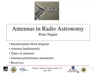
Antennas in Radio Astronomy. Peter Napier. Outline. Interferometer block diagram Antenna fundamentals Types of antennas Antenna performance parameters Receivers. Interferometer Block Diagram. Antenna Front End IF Back End Correlator. E.g., VLA observing at 4.8 GHz (C band).

E N D
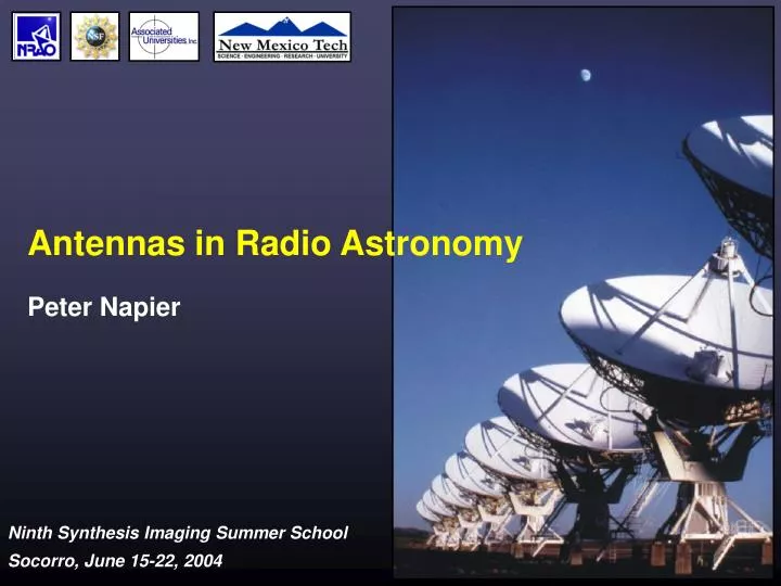
Antennas in Radio Astronomy Peter Napier
Outline • Interferometer block diagram • Antenna fundamentals • Types of antennas • Antenna performance parameters • Receivers P. Napier, Ninth Synthesis Imaging Summer School, June 15-22 2004
P. Napier, Ninth Synthesis Imaging Summer School, June 15-22 2004
Interferometer Block Diagram Antenna Front End IF Back End Correlator E.g., VLA observing at 4.8 GHz (C band) P. Napier, Ninth Synthesis Imaging Summer School, June 15-22 2004
Importance of the Antenna Elements • Antenna amplitude pattern causes amplitude to vary across the source. • Antenna phase pattern causes phase to vary across the source. • Polarization properties of the antenna modify the apparent polarization of the source. • Antenna pointing errors can cause time varying amplitude and phase errors. • Variation in noise pickup from the ground can cause time variable amplitude errors. • Deformations of the antenna surface can cause amplitude and phase errors, especially at short wavelengths. P. Napier, Ninth Synthesis Imaging Summer School, June 15-22 2004
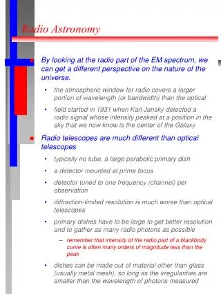
General Antenna Types Wavelength > 1 m (approx) Wire Antennas Dipole Yagi Helix or arrays of these Wavelength < 1 m (approx) Reflector antennas Wavelength = 1 m (approx) Hybrid antennas (wire reflectors or feeds) Feed P. Napier, Ninth Synthesis Imaging Summer School, June 15-22 2004
Basic Antenna Formulas Effective collecting area A(n,q,f) m2 On-axis response A0 = hA h=aperture efficiency Normalized pattern (primary beam) A(n,q,f) = A(n,q,f)/A0 Beam solid angle WA= ∫∫ A(n,q,f) dWn = frequency all sky l= wavelength A0 WA = l2 P. Napier, Ninth Synthesis Imaging Summer School, June 15-22 2004
Aperture-Beam Fourier Transform Relationship f(u,v) = complex aperture field distribution u,v = aperture coordinates (wavelengths) F(l,m) = complex far-field voltage pattern l = sinqcosf , m = sinqsinf F(l,m) = ∫∫aperturef(u,v)exp(2pi(ul+vm)dudv f(u,v) = ∫∫hemisphereF(l,m)exp(-2pi(ul+vm)dldm For VLA: q3dB = 1.02/D, First null = 1.22/D, D = reflector diameter in wavelengths P. Napier, Ninth Synthesis Imaging Summer School, June 15-22 2004
Primary Antenna Key Features P. Napier, Ninth Synthesis Imaging Summer School, June 15-22 2004
Types of Antenna Mount + Beam does not rotate + Lower cost + Better tracking accuracy + Better gravity performance - Higher cost - Beam rotates on the sky - Poorer gravity performance - Non-intersecting axis P. Napier, Ninth Synthesis Imaging Summer School, June 15-22 2004
Beam Rotation on the Sky Parallactic angle P. Napier, Ninth Synthesis Imaging Summer School, June 15-22 2004
Reflector Types Prime focus Cassegrain focus (GMRT) (AT) Offset Cassegrain Naysmith (VLA) (OVRO) Beam Waveguide Dual Offset (NRO) (ATA) P. Napier, Ninth Synthesis Imaging Summer School, June 15-22 2004
Reflector Types Prime focus Cassegrain focus (GMRT) (AT) Offset Cassegrain Naysmith (VLA) (OVRO) Beam Waveguide Dual Offset (NRO) (ATA) P. Napier, Ninth Synthesis Imaging Summer School, June 15-22 2004
VLA and EVLA Feed System Design P. Napier, Ninth Synthesis Imaging Summer School, June 15-22 2004
Antenna Performance Parameters Aperture Efficiency A0 = hA, h=hsf´hbl´hs´ht´hmisc hsf = reflector surface efficiency hbl = blockage efficiency hs = feed spillover efficiency ht = feed illumination efficiency hmisc= diffraction, phase, match, loss hsf = exp(-(4ps/l)2) e.g., s = l/16 , hsf = 0.5 rms error s P. Napier, Ninth Synthesis Imaging Summer School, June 15-22 2004
Antenna Performance Parameters Primary Beam l=sin(q), D = antenna diameter in contours:-3,-6,-10,-15,-20,-25, wavelengths -30,-35,-40 dB dB = 10log(power ratio) = 20log(voltage ratio) For VLA: q3dB = 1.02/D, First null = 1.22/D pDl P. Napier, Ninth Synthesis Imaging Summer School, June 15-22 2004
Antenna Performance Parameters Dq Pointing Accuracy Dq=rms pointing error Often Dq<q3dB/10 acceptable Because A(q3dB /10) ~ 0.97 BUT, at half power point in beam A(q3dB/2 ±q3dB/10)/A(q3dB/2) = ±0.3 For best VLA pointing use Reference Pointing. Dq=3 arcsec = q3dB/17 @ 50 GHz q3dB Primary beam A(q) P. Napier, Ninth Synthesis Imaging Summer School, June 15-22 2004
Antenna Pointing Design Subreflector mount Reflector structure Quadrupod El encoder Alidade structure Rail flatness Foundation Az encoder P. Napier, Ninth Synthesis Imaging Summer School, June 15-22 2004
ALMA 12m Antenna Design Surface: s = 25 mm Pointing: Dq = 0.6 arcsec Carbon fiber and invar reflector structure Pointing metrology structure inside alidade P. Napier, Ninth Synthesis Imaging Summer School, June 15-22 2004
Antenna Performance Parameters Polarization Antenna can modify the apparent polarization properties of the source: • Symmetry of the optics • Quality of feed polarization splitter • Circularity of feed radiation patterns • Reflections in the optics • Curvature of the reflectors P. Napier, Ninth Synthesis Imaging Summer School, June 15-22 2004
Off-Axis Cross Polarization Cross polarized Cross polarized aperture distribution primary beam VLA 4.8 GHz cross polarized primary beam P. Napier, Ninth Synthesis Imaging Summer School, June 15-22 2004
Antenna Holography VLA 4.8 GHz Far field pattern amplitude Phase not shown Aperture field distribution amplitude. Phase not shown P. Napier, Ninth Synthesis Imaging Summer School, June 15-22 2004
Receivers Receiver Matched load Temp T (oK) Gain GB/W Pout=G*Pin Pin Noise Temperature Pin = kBT (W), kB = Boltzman’s constant (1.38*10-23 J/oK) When observing a radio source Ttotal = TA + Tsys Tsys = system noise when not looking at a discrete radio source TA = source antenna temperature TA = AS/(2kB) = KS S = source flux (Jy) SEFD = system equivalent flux density SEFD = Tsys/K (Jy) Rayleigh-Jeans approximation EVLA Sensitivities P. Napier, Ninth Synthesis Imaging Summer School, June 15-22 2004
Corrections to Chapter 3 of Synthesis Imaging in Radio Astronomy II Equation 3-8: replace u,v with l,m Figure 3-7: abscissa title should be pDl P. Napier, Ninth Synthesis Imaging Summer School, June 15-22 2004