Download
1 / 1
20 likes | 372 Views
Exit air. MOCS WORKING DIAGRAM PBL-7-98. CWR 103 F. Cooling tower. COOLING TOWER. Ambient air 85 F 80 % RH. Pump 3. WATER. Flash tank. MIXED. CWS 75 F. H2. H2 Acetone 2-Propanol. Compressor 1. condenser. Pump 1. Acetone. Acetone 2-prop. endo reactor.

E N D
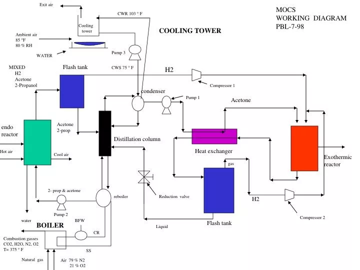
Exit air MOCS WORKING DIAGRAM PBL-7-98 CWR 103 F Cooling tower COOLING TOWER Ambient air 85 F 80 % RH Pump 3 WATER Flash tank MIXED CWS 75 F H2 H2 Acetone 2-Propanol Compressor 1 condenser Pump 1 Acetone Acetone 2-prop endo reactor Distillation column Heat exchanger Hot air Cool air Exothermic reactor gas 2- prop & acetone reboiler Reduction valve H2 Pump 2 Compressor 2 water BFW Flash tank BOILER Liquid CR Combustion gasses CO2, H2O, N2, O2 T= 375 F SS Natural gas Air 79 % N2 21 % O2