Download
1 / 32
320 likes | 437 Views
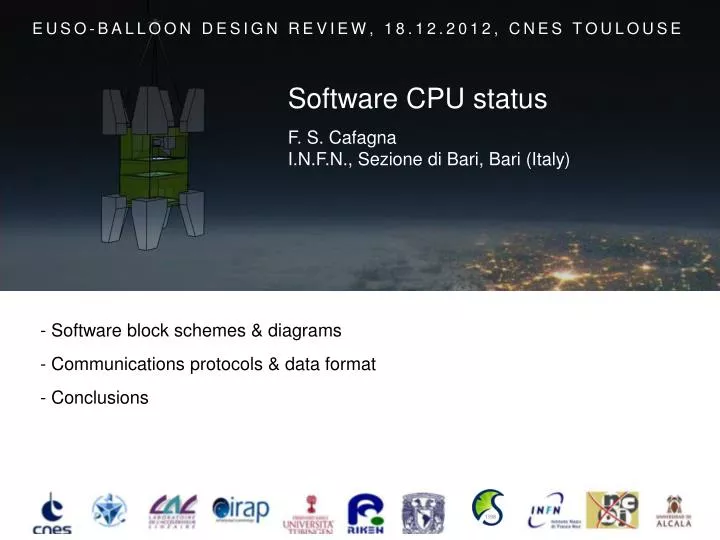
EUSO-BALLOON DESIGN REVIEW, 18.12.2012, CNES TOULOUSE. Software CPU status. F. S. Cafagna I.N.F.N., Sezione di Bari, Bari (Italy). - Software block schemes & diagrams - Communications protocols & data format - Conclusions. A brief overview & block scheme. User Space.

E N D
EUSO-BALLOON DESIGN REVIEW, 18.12.2012, CNES TOULOUSE Software CPU status F. S. Cafagna I.N.F.N., Sezione di Bari, Bari (Italy) • - Software block schemes & diagrams • - Communications protocols & data format • - Conclusions
A brief overview & block scheme User Space User InterfacesLayer. Telemetry, Console & GUI, Remote access, etc. etc. Manager Layer. Run Control FSM, Messages, Configurations etc. etc. Hardware InterfacesLayer. Drivers, Readoutunits, etc. etc. KernelSpace Software CPU status
From the DP block scheme … Software CPU status
.. CPU has been extracted, interfaces … Software CPU status
… & communication factorized Software CPU status
CPU software block scheme User Interfaces & Telemetry layer Processes Managers layer Hardware Interfaces & drivers layers Software CPU status
CPU software block scheme • Control Manager (Run Control) • Implements the Run Control and supervises the whole software operations. • Message Manager • Marshals and routes messages between software blocks. • Data Manager • Provides services to efficiently manage the data handling, storage and transmission to ground. • Event Builder • Merges CCB, CLKB and all other relevant data into an event frame and check for consistency. • Configuration Manager • Stores, updates and handles configurations for all subsystems and software blocks. • Log Manager • Provides a log service to all the software blocks that need it. Software CPU status
CPU software block scheme • Readout Unit Interface (RUI) • Communicates with blocks external to the CPU and manages the data & command flows to and from them. • Data Unit Interface (DUI) • It is a special RUI dedicated to the data I/O. It is directly interfaced to the SATA or the Ethernet interfaces. • Telemetry User Interface (TUI) • Handles the command and data transmissions between the telemetry system (SIREN) and the CPU. • User Interface (UI) • Implements the communications with user and controls when the telemetry system is not connected. Software CPU status
CPU software blocks scheme Polling the CLK for triggers Request data from CCB, CLK Transfer data to disk &/or telemetry Software CPU status
Run control Finite State Machine (FSM) Software CPU status
Run control Finite State Machine (FSM) Software CPU status
User Scenario: Normal Data Acquisition Software CPU status
User Scenario: Normal Data Acquisition User changes detector parameters User operates runs and calibrations Quicklook& Telemetry Software CPU status
Activity diagram: Normal Data Acquisition Software CPU status
Activity diagram: Normal Data Acquisition Software CPU status
Activity diagram: Normal Data Acquisition Software CPU status
Activity diagram: Normal Data Acquisition Software CPU status
Activity diagram: Normal Data Acquisition Software CPU status
Activity diagram: Normal Data Acquisition Software CPU status
Activity diagram: Normal Data Acquisition Software CPU status
Activity diagram: Normal Data Acquisition Software CPU status
Activity diagram: Normal Data Acquisition Software CPU status
Activity diagram: Normal Data Acquisition Software CPU status
Activity diagram: Normal Data Acquisition Software CPU status
Activity diagram: Normal Data Acquisition Software CPU status
Activity diagram: Normal Data Acquisition Software CPU status
Activity diagram: Normal Data Acquisition Software CPU status
Activity diagram: Normal Data Acquisition Software CPU status
Communications with HK • Communication between CPU and HK. • Low level protocol: RS422; serial point to point, master-slave protocol. • HK is the slave and respond only upon CPU request. • CRC16 will be used to check for data corruption during transmission from and to HK. • HK data format • Data are 16 bit words while commands are encoded into a 8 bit word. • The packet size range from a minimum of 5 Bytes to a maximum of 8 Bytes. Software CPU status
Communications with CCB (PDM) • Communications between CPU and CCB • Low level protocol: SpaceWire; full-duplex. • Messages transmitted by the CCB to the CPU includes a CRC-32 (IEEE 802.3, Ethernet). • CCB interfaces the CPU with the PDM and the SPACIROCs attached to the latter. Both command and data packets must be exchanged to configure the boards and chips, and readout physics data (~330kB/event). • CCB (PDM) data format • Commands are simple actions on the boards or write/read register requests on boards and chips. Different commands may have different associate parameters (data). Software CPU status
Communications with CLKB • Communications between CPU and CLKB • Low level protocol: SpaceWire; full-duplex. • Messages transmitted by the CLKB to the CPU includes a CRC-32 (IEEE 802.3, Ethernet). • CLKB interfaces the CPU with the GPS board. • Both command and data packets must be exchanged to configure the boards, and readout GPS and trigger data (~800B/event). • CLKB data format • Both trigger status and GPS data are transmitted by the CLKB to the CPU. • Trigger status data can be transmitted standalone: • Or togheter with the GPS ones: Software CPU status
Conclusions • Hardware interface backbone layer developed (Spacewire, RS422) and extensive performance tests, to monitor failure rates and spot bottlenecks, are in progress. • The low level drivers and communication protocols have been tested on the flight CPU and the data acquisition chain proven to work. • The most critical part was related to the SpaceWire driver that is in charge for the bulk data exchange between the CPU and CCB. This driver is actually understood and the data transfer rate between the CCB and the CPU is almost the maximum one reachable with the SpaceWire protocol. • The low level packet formats of both commands and data have been defined for all DP components. • Continuous feedback to and from the developers to define hardware block working modes, configuration parameters, command lists etc. etc., and debug and fine tune the firmware of the HK, CCB and CLKB. Software CPU status