Download
1 / 19
190 likes | 289 Views
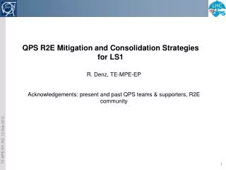
ELQA activities during LS1. DFB Instrumentation Upgrade Cabling Issues R2E Consolidation Current Lead Insulation Project. DFB Instrumentation Upgrade Cabling Issues R2E Consolidation Current Lead Insulation Project. R2E Consolidation Galvanic Insulation of DC Cables

E N D
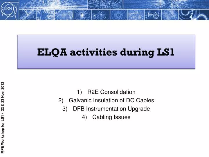
ELQA activities during LS1 • DFB Instrumentation Upgrade • Cabling Issues • R2E Consolidation • Current Lead Insulation Project • DFB Instrumentation Upgrade • Cabling Issues • R2E Consolidation • Current Lead Insulation Project • R2E Consolidation • Galvanic Insulation of DC Cables • DFB Instrumentation Upgrade • Cabling Issues • DFB Instrumentation Upgrade • Cabling Issues • R2E Consolidation • Current Lead Insulation Project
1) R2E Consolidation • Activity Overview and Impact: • Following LS1, high levels of radiation expected at P1, P5, P7 & P8 which will induce Single Event Errors (SEE) in standard electronics. • Following testing in CNGS we are aware that the regulators of our Current Lead Heating System cubicles cannot stand the predicted radiation levels that will be seen in UJ14, UJ16 & UJ56. • Hence, we have 3 cubicles which will need to be relocated. • Why During LS1?: • 15 Power Converters along with many other equipment cubicles will be moved. Obviously, such a large project can only be performed during a shutdown. • Time Period: • The overall implementation of the project during LS1 is estimated at 57 weeks. The R2E schedule begins in line with LS1, the first locations being P1 & P8.
R2E Relocation at Point 1 UJ14 & UJ16: Current location of Racks DYXA01 & DYXB01 US15 Level 2: Position of Rack DYXA01 & DYXB01 after equipment relocation.
R2E Relocation at Point 5 UJ56: Current location of rack DYXF01 USC55: Position of Rack DYXF01 after relocation. We already have Rack DYXE01 installed in the same area.
R2E Consolidation • Tasks & Manpower: • Disconnection and storage of the individual chassis will be our responsibility as well as reinstating and testing the equipment following the relocation. • All heater chassis will be stored in building 282 while the rack is relocated. • All ELQA activities are planned within the R2E project schedule and will be managed internally by the ELQA team (Giorgio, Mateusz, Stephen, Greg, Richard + Polish collaboration). • ELQA has a 3 week window within the R2E project for re-installation and re-commissioning. This time frame is not restricted by other following activities thus can be fitted around other higher priority work. • We do not require support from other MPE sections. • There are no missing resources to consider. • Contributions from other groups: • EN-EL team are performing the re-cabling as well as fitting the new connectors. • All cabling (non-standard T/C cable) and connector pins have been delivered to CERN.
R2E Consolidation • Safety Measures: • Personal: • All power will have been removed before we remove the chassis. • The chassis are not heavy thus can be moved easily. • However, care will need to be taken when ascending and descending the narrow stairwells whilst carrying the chassis. • Equipment: • The chassis contain electronics so care should be taken when handling. • Transportation methods and routes will need to be premeditated to ensure no damage to the equipment. No showstoppers or potential issues foreseen
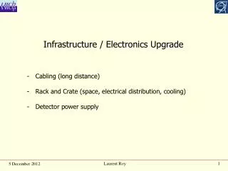
2) Galvanic Insulation of DC Cables • Activity Overview & Impact: • As part of the work and testing which takes place during LS1 it is required to disconnect and isolate all DC cables from their respective Current Leads. • The DC cables and Current Leads will be left in this state for the duration of the shutdown. • When the DC cables are disconnected from the Current Leads both parts are then susceptible to harmful manipulations and damage, this risk being multiplied when large volumes of work are taking place around the DFB’s. • Hence, this extended period of separation required a new long-term approach which would allow us to reconnect the DC cables to the Current Leads to avoid damage and mishandling, whilst maintaining a high quality of insulation between the cable and lead.
Galvanic Insulation of DC Cables • Activity Overview & Impact: • We have also decided to improve the connection process for ELQA testing by installing two female 4mm banana plug connection points on each current lead. • Current ELQA test cables have crocodile clips for connection to the current leads, these will be replaced with 4mm male banana plugs. • This assembly then provides us with a well insulated, safe and secure electrical connection which can be used throughout LS1.
Galvanic Insulation of DC Cables • Time Period: • Installation of the Current Lead Insulation pieces will take place during the first few weeks of the shutdown. This will be done simultaneously with the DC cable disconnection contained within the LS1 schedule. • Removal will take place when the DC Cables are reconnected prior to hardware commissioning. • Tasks & Manpower: • The disconnection of the Current Leads along with the installation of the insulation pieces will be managed internally within the ELQA team (Giorgio, Mateusz, Stephen, Greg, Richard + Polish collaboration) as per normal during shutdowns. • We do not require support from other MPE sections or any other groups. • There are no missing resources to consider. • Status: • All the Polycarbonate insulation pieces have been ordered from a German company and should be with us mid-December. • All fasteners, connectors and fixings have been ordered with a large majority already delivery.
Galvanic Insulation of DC Cables • Safety Measures: • Personal: • Before touching the Current Leads the associated Power Converters should be ‘consigné’. • Equipment: • Care should be taken when manipulating the Cable/Lead assembly as there are brittle ceramic parts within the current lead assembly. • Due to lack of space, when installing the 600A insulation pieces due care should taken as to not disturb the Fischer connector at the rear. No showstoppers or potential issues foreseen
3) DFB Instrumentation Upgrade: Fischer 120A • Activity & Impact: • Fischer 16 pin connector on the 120A chimneys experienced a breakdown during ELQA testing (NC 831928) at around 400V (due to the low dielectrical strength of Helium). • ELQA diagnostic localized the fault at the level of the cold voltage tap connector on top of the current lead chimney. • The fault has been reproduced at warm before and after dismantling the connector. The Fischer connector has been qualified to 2kV between pins for 180 seconds in normal atmospheric conditions. • The proposal from Philippe Denis is to surround the connections with an insulative epoxy resin to avoid sparking between pins. • If not done during LS1 the affected circuits could only be ELQA tested to 200V. • Time period: • This has not been defined yet by TE-MSC/TE-CRG, who will be responsible for the upgrade. • Thus, it is currently not incorporated in the LS1 schedule.
DFB Instrumentation Upgrade: Fischer 120A • Manpower: • The involvement of the ELQA team will be to re-qualify the connectors following the upgrade as part of the normal ELQA campaign (foreseen to be tested up to 1100V). • No missing resources or support foreseen. • Contributions from other groups: • Amalia Ballarino’s section TE-MSC or Antonio Perin’s section TE-CRG will be responsible for the design and execution of the upgrade. With respect to the tasks apportioned to the ELQA team, no showstoppers or potential issues are foreseen
DFB Instrumentation Upgrade: 13kA TT’s • Activity & Impact: • Due to breakdowns during ELQA qualification of the RB circuits there will be an upgrade of the Canon C50 connector which routes the current lead temperature signals to the cryogenic monitoring equipment. • We currently test to 1.7kV with C50 connector in place. Following the upgrade it will be possible to ELQA test the RB circuit up to 2.1kV with all cryogenic instrumentation attached. • This activity is planned during LS1 due to the invasive nature of the work. • Time period: • This upgrade will run from June 2013 to May 2014. Canon C50 connector Proximity Equipment
DFB Instrumentation Upgrade: 13kA TT’s • Tasks & Manpower: • The Canon C50 connector (50V) of the RB line will be replaced by a Lemo/Redel S series 51 pin assembly (3kV). • ELQA team will internally manage the upgrade of the PE side of the connector. • The connector will be tested following replacement then fully tested to 2.1kV during the normal ELQA campaign. • We do not require support from other MPE sections or any other groups. • There are no missing resources to consider. • Status: • All 16 connectors have been delivered. • When mounting on the Proximity Equipment a small metal plate will compensate for the difference in size of connectors. This will be manufactured over the coming weeks.
DFB Instrumentation Upgrade: 13kA TT’s • Contributions from other groups: • TE-CRG are responsible for upgrading the cable side of the connector. • Safety Measures: • Personal: • Care should be taken due to working at height. • Equipment: • Care should be taken to ensure minimal disruption to the internal wiring of the Proximity Equipment. • Any drilling or filing, etc. should be performed on the ground to avoid foreign material entering the PE. With respect to the tasks apportioned to the ELQA team, no showstoppers or potential issues are foreseen
4) Cabling Issues: DFBA Consolidation at Point 5 • Activity & Impact: • As with the rest of the main circuits of the LHC, shunts will be added to all 13kA splices in the DFBA’s. Most can be upgraded in-situ but there are special cases where the DFBA must be moved due to lack of space. • Time Period: • The estimated time duration for the complete DFBAK consolidation is 10 weeks. • It is currently not incorporated in the LS1 schedule. • Tasks & Manpower: • ELQA will be involved in the disconnection and securing of instrumentation cabling prior to the movement of the DFBAK at P5; then the reconnection of cabling following the consolidation. • All ELQA team activities for the project will be managed internally.
Cabling Issues: DFBA Consolidation at Point 5 • Tasks & Manpower cont’d: • There are no missing resources to consider. • No support is required from other MPE sections. • Contributions from other groups: • Project being managed by Antonio Perin TE-CRG, first coordination meeting took place on 17th October 2012. • There will be input from a range of other groups as there is extensive lifting and transportation activities to consider. With respect to the tasks apportioned to the ELQA team, no showstoppers or potential issues are foreseen
Thank you Any Questions?