Download
1 / 13
140 likes | 281 Views
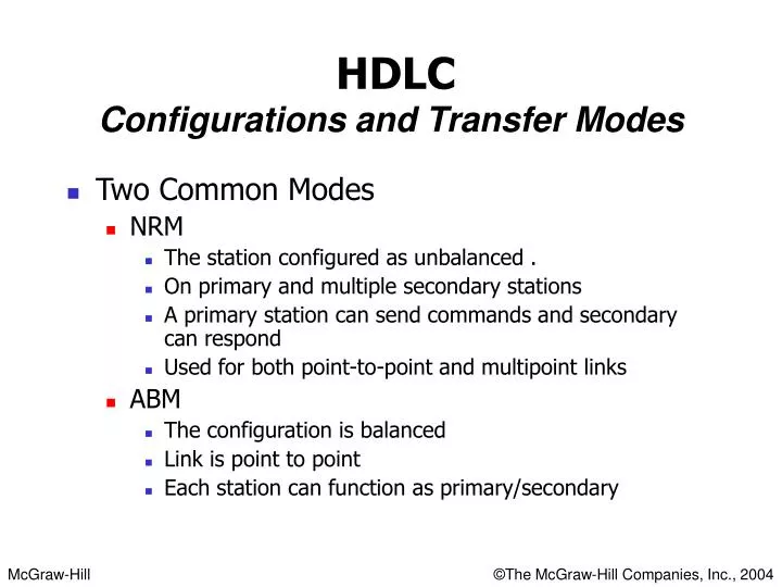
Two Common Modes NRM The station configured as unbalanced . On primary and multiple secondary stations A primary station can send commands and secondary can respond Used for both point-to-point and multipoint links ABM The configuration is balanced Link is point to point

E N D
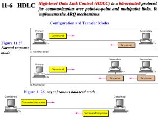
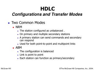
Two Common Modes NRM The station configured as unbalanced . On primary and multiple secondary stations A primary station can send commands and secondary can respond Used for both point-to-point and multipoint links ABM The configuration is balanced Link is point to point Each station can function as primary/secondary HDLCConfigurations and Transfer Modes
Frames • Three types of frames • I-frames(Information frames) • To transport user data or control information for user data like piggy backing • S-frames(Supervisory frames) • To transport Control frames • U-frames(Unnumbered frames) • For link management
Flag Field It is an 8-bit sequence with a bit pattern of 01111110 Identify start and end of the frame Serve for the synchronization Bi stuffing is used to avoid the appearance of this number in that data Address field Address of the secondary station Whether the station is the originator or the destination If primary creates the frame it contains “to” otherwise “from” It can be 1 or several byte long Always the last bit ends with 1 If more than one byte all byte’s last bit ,except the last byte ,will end with 0. Ethernet does not use primary/secondary environment ,uses two address fields Sender address Receiver address Fields
Control Field 1 or 2 byte Used for error and flow control Interpretation is different for different frame types Information Field User’s data from the network layer or Network management information layer Length can vary but fixed for one network FCS Frame check sequence It contain 2 or 4 byte ITU-T CRC Fields
FRAME TYPES • I-frame
Example 3 Figure 11.22 shows an exchange using piggybacking where is no error. Station A begins the exchange of information with an I-frame numbered 0 followed by another I-frame numbered 1. Station B piggybacks its acknowledgment of both frames onto an I-frame of its own. Station B’s first I-frame is also numbered 0 [N(S) field] and contains a 2 in its N(R) field, acknowledging the receipt of A’s frames 1 and 0 and indicating that it expects frame 2 to arrive next. Station B transmits its second and third I-frames (numbered 1 and 2) before accepting further frames from station A. Its N(R) information, therefore, has not changed: B frames 1 and 2 indicate that station B is still expecting A frame 2 to arrive next.
Example 4 In Example 3, suppose frame 1 sent from station B to station A has an error. Station A informs station B to resend frames 1 and 2 (the system is using the Go-Back-N mechanism). Station A sends a reject supervisory frame to announce the error in frame 1. Figure 11.23 shows the exchange.